AC7 OPTO 22, AC7 Datasheet - Page 30
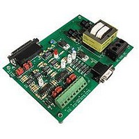
AC7
Manufacturer Part Number
AC7
Description
Computers, Interface Cards
Manufacturer
OPTO 22
Specifications of AC7
Peak Reflow Compatible (260 C)
No
Leaded Process Compatible
No
Features
RS232 To RS422 Converter
Interface
RS-422⁄485
Module Type
Adapter Card
Mounting Type
Protective Enclosure
Voltage, Supply
115 VAC ± 10 VAC @ 50⁄60 Hz
Lead Free Status / RoHS Status
Contains lead / RoHS non-compliant
Available stocks
Company
Part Number
Manufacturer
Quantity
Price

Part Number:
AC713
Manufacturer:
ALPHA
Quantity:
20 000
Part Number:
AC7201-50JC
Manufacturer:
AMD
Quantity:
20 000
Part Number:
AC744
Manufacturer:
SKYWORKS/思佳讯
Quantity:
20 000
Company:
Part Number:
AC76951
Manufacturer:
ALPHA
Quantity:
5 510
Part Number:
AC7C4096B012TCN
Manufacturer:
ALLIANCE
Quantity:
20 000


USING MULTIPLE AC7A/B UNITS ON ONE LINK
30 AC7A/B User’s Guide
Background
Optomux uses a 4-wire RS-422/485 communication system. Technically, this 4-wire RS-422/485 link is 2 links using
the same 2-pair communication cable.
The pair of wires connected from the AC7A/B RS-422/485 transmitter to the Optomux receivers represents the
RS-422 portion. With RS-422, there can only be one transmitter on a link (twisted pair) because the RS-422
transmitter is always enabled. RS-422 requires termination, but not biasing.
The pair of wires connected to the AC7A/B RS-422/485 receiver from the Optomux transmitters represents the
RS-485 portion. With RS-485, there can be multiple transmitters on the same link (twisted pair) because the
RS-485 transmitters are always disabled when not actively transmitting. RS-485 requires both termination and
biasing.
The AC7A/B was designed as an RS-232 to RS-422/485 converter to be used between a computer and an Optomux
I/O system. This assumes there will only be one AC7A/B on the link and that the AC7A/B RS-422/485 transmitter
is only connected to Optomux brain receivers. This means that the AC7A transmitter can be used with the default
configuration of being RS-422. This configuration does not bias the RS-422 link, and the AC7A transmitter stays
enabled at all times, even when not transmitting. Because of this, there can only be one transmitter on this (RS-422)
twisted pair.
Description
Whenever there are multiple AC7A/Bs on a link, special configuration of the AC7A/B’s is required. With multiple
AC7A/Bs in the system, there will be multiple transmitters connected on the RS-422 portion of some or all of the
AC7A/B’s. In order for this to work, each AC7A/B must be configured so that the RS-422 portion is setup in RS-485
mode. In other words, the RS-422 transmitters on the AC7A/B’s must be configured to be disabled when not
actively transmitting in order to prevent interference with the other AC7A/B RS-422 transmitters.
In addition, because the AC7A/B’s transmitters are now connected on an RS-485 link, the termination and biasing
requirements for the RS-422/485 transmitter side of the AC7A/B’s are different than when the AC7A/B’s are used
in their default configuration. The twisted pair cable connected to the transmitter side of the AC7A/B’s must be
biased in one location only and terminated at both ends of the link.
Related parts for AC7
Image
Part Number
Description
Manufacturer
Datasheet
Request
R

Part Number:
Description:
Standard AC Input Module, 180 To 280 VAC Input Voltage Range, Voltage Input, 15 MA Output Current, 12 To 18 VDC Output Voltage, General
Manufacturer:
OPTO 22
Datasheet:

Part Number:
Description:
AC Output Module
Manufacturer:
OPTO 22
Datasheet:

Part Number:
Description:
SSR, PANEL MOUNT, 280VAC, 32VDC, 10A
Manufacturer:
OPTO 22
Datasheet:

Part Number:
Description:
SSR, PANEL MOUNT, 280VAC, 32VDC, 25A
Manufacturer:
OPTO 22
Datasheet:
Part Number:
Description:
SSR, PANEL MOUNT, 280VAC, 32VDC, 25A
Manufacturer:
OPTO 22
Datasheet:
Part Number:
Description:
SSR, PANEL MOUNT, 280VAC, 32VDC, 45A
Manufacturer:
OPTO 22
Datasheet:
Part Number:
Description:
SSR, PANEL MOUNT, 280VAC, 32VDC, 45A
Manufacturer:
OPTO 22
Datasheet:

Part Number:
Description:
Solid State Relays, Accessories
Manufacturer:
OPTO 22
Datasheet:
