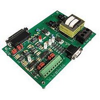
AC7 OPTO 22, AC7 Datasheet - Page 33

AC7
Manufacturer Part Number
AC7
Description
Computers, Interface Cards
Manufacturer
OPTO 22
Specifications of AC7
Peak Reflow Compatible (260 C)
No
Leaded Process Compatible
No
Features
RS232 To RS422 Converter
Interface
RS-422⁄485
Module Type
Adapter Card
Mounting Type
Protective Enclosure
Voltage, Supply
115 VAC ± 10 VAC @ 50⁄60 Hz
Lead Free Status / RoHS Status
Contains lead / RoHS non-compliant
Available stocks
Company
Part Number
Manufacturer
Quantity
Price
Part Number:
AC713
Manufacturer:
ALPHA
Quantity:
20 000
Part Number:
AC7201-50JC
Manufacturer:
AMD
Quantity:
20 000
Part Number:
AC744
Manufacturer:
SKYWORKS/思佳讯
Quantity:
20 000
Company:
Part Number:
AC76951
Manufacturer:
ALPHA
Quantity:
5 510
Part Number:
AC7C4096B012TCN
Manufacturer:
ALLIANCE
Quantity:
20 000
ADDITIONAL TECHNICAL INFORMATION
While this system of handshaking signals works well, it can become troublesome when the communication is not
between a computer and a modem. Oftentimes, one piece of equipment may not need nor use these hardware flow
control signals, while the other piece of equipment requires hardware flow control. The device that expects
hardware handshaking signals will not communicate until it receives the appropriate signals. To resolve such
problems, appropriate pins may be wired together to trick a device into thinking that its counterpart is sending the
required handshaking signals. One method is to wire RTS to CTS, and wire together DSR, DCD, and DTR on the
devices’ RS-232 serial port. Connecting RTS to CTS tells the computer that it can send data whenever it wants to.
Connecting together DSR, DCD, and DTR means that the computer or modem will always think that the other device
is online and ready to communicate.
Using Protective Ground on AC7A/B
Pin 1, protective ground on the 25-pin connector, can be tied to the terminal marked GND on the AC7A/B adapter
card by installing the jumper labeled JX. This is not normally used. This is only necessary if protective ground is being
used and is not grounded on the host computer end. Newer AC7A/Bs do not have a JX jumper.
BIASING AND TERMINATING RS-422/485
RS-485 uses two wires for each data line. The data signal is transmitted as the difference in voltage between
the two wires that make up a single data line. Which of these two wires has the higher voltage determines
whether the wires carry a DIGITAL ON or DIGITAL OFF. Unlike RS-232, RS-485 allows more than one transmitter
and/or receiver on a single data line. These two characteristics are the reason that biasing and termination are
required on an RS-485 communication line.
Note: RS-422 is very similar to RS-485. The key difference is that RS-422 allows one (and only one) transmitter
and multiple receivers on a single data line.
The RS-485 network is composed of two wires that comprise a single, main transmission “bus” or “trunk” line, with
transmitters and receivers connected along the central line. Terminating resistors are needed at the two ends of this
main line. Usually, this is done at the devices located at the physical ends of the line. Since the AC7A/B is usually
located at the beginning or end of an RS-485 transmission line, the AC7A/B is usually the location for one of the
termination resistors. However, a resistor doesn’t physically have to be added, because the AC7A/B contains
terminating resistors. Installing the appropriate jumper (B2, B4, C2, or C4) on the AC7A/B connects the termination
resistor to the transmission line.
Sometimes the AC7A/B is placed in the middle of the RS-485 trunk, in which case the terminating jumper should
not be installed.
Because the outputs of more than one RS-485 transmitter may be tied together on the communication line, they
cannot all be actively driving the line at the same time. Thus, no more than one transmitter is actually sending signals
at any given time; the others in a sense electrically disconnect from the network (though they still represent a load
on whoever is driving the network). This condition is called disabling the transmitter, or disabling the driver.
The enabling/disabling of the transmitter (TO) on the AC7A/B can be configured to be controlled by RTS or CTS.
AC7A/B User’s Guide 33


