AC7 OPTO 22, AC7 Datasheet - Page 25
AC7
Manufacturer Part Number
AC7
Description
Computers, Interface Cards
Manufacturer
OPTO 22
Specifications of AC7
Peak Reflow Compatible (260 C)
No
Leaded Process Compatible
No
Features
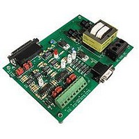
RS232 To RS422 Converter
Interface
RS-422⁄485
Module Type
Adapter Card
Mounting Type
Protective Enclosure
Voltage, Supply
115 VAC ± 10 VAC @ 50⁄60 Hz
Lead Free Status / RoHS Status
Contains lead / RoHS non-compliant
Available stocks
Company
Part Number
Manufacturer
Quantity
Price

Part Number:
AC713
Manufacturer:
ALPHA
Quantity:
20 000
Part Number:
AC7201-50JC
Manufacturer:
AMD
Quantity:
20 000
Part Number:
AC744
Manufacturer:
SKYWORKS/思佳讯
Quantity:
20 000
Company:
Part Number:
AC76951
Manufacturer:
ALPHA
Quantity:
5 510
Part Number:
AC7C4096B012TCN
Manufacturer:
ALLIANCE
Quantity:
20 000


General guidelines for using an AC7A/B with other RS-422/485 devices:
a. The RS-422/485 screw terminals on the AC7A/B are labeled TO+, TO-, FO+, and FO- . This labeling
b. The RTS and CTS terminals are used for hardware handshaking (flow control). RTS± are outputs from the
c. The AC7A/B was designed to communicate in 4-wire RS-422/485 mode. In the 4-wire mode uses two
d. In most applications, the AC7A/B can also be used in 2-wire RS-485 mode. In the 2-wire mode uses one
convention is for Opto 22’s Optomux I/O. For use with devices other than Opto 22’s Optomux I/O,
the following convention applies to the RS-485 port of the AC7A/B
AC7A/B. CTS± are inputs into the AC7A/B.
twisted-pairs of wiring (four conductors total) are used for communication. In 4-wire mode, one twisted-
pair of wires is used for the transmit signal and the other twisted pair of wires is used for the receive
signal. One additional pair (pair #3) of wires is used to connect the LOGIC GND of the AC7A/B to the
COM terminal of the RS-422/485 device.
twisted-pair of wiring (two conductors total) is used for communication. In 2-wire mode, the same twisted-
pair of wires is used for the transmit signal and the receive signal. One additional pair (pair #2) of wires is
used to connect the LOGIC GND of the AC7A/B to the COM terminal of the RS-485 device. To use the
AC7A/B in two wire mode, see the section titled Two-Wire RS-485 Mode (page 25).
Figure 3-14: RS-422/485 Cabling Diagram (alternative, less noise immune)
TO+ = Transmit+
TO- = Transmit-
FO+ = Receive+
FO- = Receive-
AC7A/B User’s Guide 25
INSTALLATION (cont.)
Related parts for AC7
Image
Part Number
Description
Manufacturer
Datasheet
Request
R

Part Number:
Description:
Standard AC Input Module, 180 To 280 VAC Input Voltage Range, Voltage Input, 15 MA Output Current, 12 To 18 VDC Output Voltage, General
Manufacturer:
OPTO 22
Datasheet:

Part Number:
Description:
AC Output Module
Manufacturer:
OPTO 22
Datasheet:

Part Number:
Description:
SSR, PANEL MOUNT, 280VAC, 32VDC, 10A
Manufacturer:
OPTO 22
Datasheet:

Part Number:
Description:
SSR, PANEL MOUNT, 280VAC, 32VDC, 25A
Manufacturer:
OPTO 22
Datasheet:
Part Number:
Description:
SSR, PANEL MOUNT, 280VAC, 32VDC, 25A
Manufacturer:
OPTO 22
Datasheet:
Part Number:
Description:
SSR, PANEL MOUNT, 280VAC, 32VDC, 45A
Manufacturer:
OPTO 22
Datasheet:
Part Number:
Description:
SSR, PANEL MOUNT, 280VAC, 32VDC, 45A
Manufacturer:
OPTO 22
Datasheet:

Part Number:
Description:
Solid State Relays, Accessories
Manufacturer:
OPTO 22
Datasheet:
