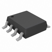
FW349-TL-E SANYO, FW349-TL-E Datasheet - Page 2

FW349-TL-E
Manufacturer Part Number
FW349-TL-E
Description
MOSFET N/P-CH 45V 5/4.5A 8-SOP
Manufacturer
SANYO
Datasheet
1.FW349-TL-E.pdf
(6 pages)
Specifications of FW349-TL-E
Fet Type
N and P-Channel
Fet Feature
Logic Level Gate
Rds On (max) @ Id, Vgs
37 mOhm @ 5A, 10V
Drain To Source Voltage (vdss)
45V
Current - Continuous Drain (id) @ 25° C
5A, 4.5A
Gate Charge (qg) @ Vgs
18.1nC @ 10V
Input Capacitance (ciss) @ Vds
860pF @ 20V
Power - Max
1.8W
Mounting Type
Surface Mount
Package / Case
8-SOP
Lead Free Status / RoHS Status
Lead free / RoHS Compliant
Vgs(th) (max) @ Id
-
Other names
869-1168-2
Available stocks
Company
Part Number
Manufacturer
Quantity
Price
Part Number:
FW349-TL-E
Manufacturer:
SANYO/三洋
Quantity:
20 000
Electrical Characteristics at Ta=25°C
Package Dimensions
unit : mm (typ)
7005-003
[N-channel]
Drain-to-Source Breakdown Voltage
Zero-Gate Voltage Drain Current
Gate-to-Source Leakage Current
Cutoff Voltage
Forward Transfer Admittance
Static Drain-to-Source On-State Resistance
Input Capacitance
Output Capacitance
Reverse Transfer Capacitance
Turn-ON Delay Time
Rise Time
Turn-OFF Delay Time
Fall Time
Total Gate Charge
Gate-to-Source Charge
Gate-to-Drain “Miller” Charge
Diode Forward Voltage
[P-channel]
Drain-to-Source Breakdown Voltage
Zero-Gate Voltage Drain Current
Gate-to-Source Leakage Current
Cutoff Voltage
Forward Transfer Admittance
Static Drain-to-Source On-State Resistance
Input Capacitance
Output Capacitance
Reverse Transfer Capacitance
Turn-ON Delay Time
Rise Time
Turn-OFF Delay Time
Fall Time
Total Gate Charge
Gate-to-Source Charge
Gate-to-Drain “Miller” Charge
Diode Forward Voltage
0.595
1
8
1.27
Parameter
5.0
5
4
0.43
V (BR)DSS
V (BR)DSS
0.2
R DS (on)1
R DS (on)2
R DS (on)1
R DS (on)2
V GS (off)
V GS (off)
Symbol
t d (on)
t d (off)
t d (on)
t d (off)
yfs
yfs
I DSS
I GSS
Coss
I DSS
I GSS
Coss
Ciss
Crss
V SD
Ciss
Crss
V SD
Qgs
Qgd
Qgs
Qgd
Qg
Qg
t r
t f
t r
t f
1 : Source1
2 : Gate1
3 : Source2
4 : Gate2
5 : Drain2
6 : Drain2
7 : Drain1
8 : Drain1
SANYO : SOP8
I D =1mA, V GS =0V
V DS =45V, V GS =0V
V GS =±16V, V DS =0V
V DS =10V, I D =1mA
V DS =10V, I D =5A
I D =5A, V GS =10V
I D =3A, V GS =4V
V DS =20V, f=1MHz
V DS =20V, f=1MHz
V DS =20V, f=1MHz
See specified Test Circuit.
See specified Test Circuit.
See specified Test Circuit.
See specified Test Circuit.
V DS =24V, V GS =10V, I D =5A
V DS =24V, V GS =10V, I D =5A
V DS =24V, V GS =10V, I D =5A
I S =5A, V GS =0V
I D =--1mA, V GS =0V
V DS =--45V, V GS =0V
V GS =±16V, V DS =0V
V DS =--10V, I D =- -1mA
V DS =--10V, I D =- -4.5A
I D =--4.5A, V GS =- -10V
I D =--3A, V GS =--4V
V DS =--20V, f=1MHz
V DS =--20V, f=1MHz
V DS =--20V, f=1MHz
See specified Test Circuit.
See specified Test Circuit.
See specified Test Circuit.
See specified Test Circuit.
V DS =--24V, V GS =- -10V, I D =--4.5A
V DS =--24V, V GS =- -10V, I D =--4.5A
V DS =--24V, V GS =- -10V, I D =--4.5A
I S =--4.5A, V GS =0V
FW349
Conditions
Electrical Connection
8
1
7
2
min
--1.2
--45
1.2
4.2
4.5
45
6
3
Ratings
typ
--0.86
1275
18.1
0.83
5
4
860
105
150
123
110
7.1
2.6
4.0
7.6
2.4
5.7
28
47
75
14
64
60
65
47
76
14
50
75
26
max
Top view
1 : Source1
2 : Gate1
3 : Source2
4 : Gate2
5 : Drain2
6 : Drain2
7 : Drain1
8 : Drain1
--2.6
--1.2
±10
±10
106
2.6
1.2
37
66
62
--1
1
No.8750-2/6
Unit
mΩ
mΩ
mΩ
mΩ
µA
µA
pF
pF
pF
nC
nC
nC
µA
µA
nC
nC
nC
pF
pF
pF
ns
ns
ns
ns
ns
ns
ns
ns
V
V
S
V
V
V
S
V


