STGB7NC60HDT4 STMicroelectronics, STGB7NC60HDT4 Datasheet - Page 3
STGB7NC60HDT4
Manufacturer Part Number
STGB7NC60HDT4
Description
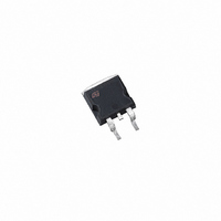
IGBT N-CHAN 25A 600V D2PAK
Manufacturer
STMicroelectronics
Series
PowerMESH™r
Datasheet
1.STGB7NC60HDT4.pdf
(15 pages)
Specifications of STGB7NC60HDT4
Voltage - Collector Emitter Breakdown (max)
600V
Vce(on) (max) @ Vge, Ic
2.5V @ 15V, 7A
Current - Collector (ic) (max)
25A
Power - Max
80W
Input Type
Standard
Mounting Type
Surface Mount
Package / Case
D²Pak, TO-263 (2 leads + tab)
Configuration
Single
Collector- Emitter Voltage Vceo Max
600 V
Collector-emitter Saturation Voltage
2.5 V
Maximum Gate Emitter Voltage
+/- 20 V
Continuous Collector Current At 25 C
10 A
Gate-emitter Leakage Current
+/- 100 nA
Power Dissipation
25 W
Maximum Operating Temperature
+ 150 C
Continuous Collector Current Ic Max
25 A
Minimum Operating Temperature
- 55 C
Mounting Style
SMD/SMT
Lead Free Status / RoHS Status
Lead free / RoHS Compliant
Igbt Type
-
Lead Free Status / Rohs Status
Lead free / RoHS Compliant
Other names
497-4108-2
Available stocks
Company
Part Number
Manufacturer
Quantity
Price
Company:

Part Number:
STGB7NC60HDT4
Manufacturer:
ST
Quantity:
12 500


ELECTRICAL CHARACTERISTICS (CONTINUED)
Table 6: Dynamic
(1) Pulsed: Pulse duration= 300 µs, duty cycle 1.5%
Table 7: Switching On
Table 8: Switching Off
Table 9: Switching Energy
(2) Eon is the turn-on losses when a typical diode is used in the test circuit in figure 2. If the IGBT is offered in a package with a co-pack
diode, the co-pack diode is used as external diode. IGBTs & DIODE are at the same temperature (25°C and 125°C)
(3) Turn-off losses include also the tail of the collector current.
Symbol
Symbol
Symbol
Symbol
Eon (2)
Eon (2)
(di/dt)
(di/dt)
E
E
g
t
t
t
t
t
t
r
r
C
off
off
C
C
Q
d
d
fs
Q
d(on)
d(on)
(V
(V
E
E
I
Q
CL
(
(
oes
t
t
res
t
t
ies
ts
ts
ge
gc
off
off
r
r
f
f
(3)
(3)
(1)
g
off
off
on
on
)
)
)
)
Turn-on Switching Losses
Turn-off Switching Loss
Total Switching Loss
Turn-on Switching Losses
Turn-off Switching Loss
Total Switching Loss
Forward Transconductance
Input Capacitance
Output Capacitance
Reverse Transfer
Capacitance
Total Gate Charge
Gate-Emitter Charge
Gate-Collector Charge
Turn-Off SOA Minimum
Current
Turn-on Delay Time
Current Rise Time
Turn-on Current Slope
Turn-on Delay Time
Current Rise Time
Turn-on Current Slope
Off Voltage Rise Time
Turn-off Delay Time
Current Fall Time
Off Voltage Rise Time
Turn-off Delay Time
Current Fall Time
Parameter
Parameter
Parameter
Parameter
V
V
V
V
(see Figure 22)
V
R
V
R
(see Figure 19)
V
R
(see Figure 20)
V
R
(see Figure 19)
V
R
(see Figure 20)
V
R
T
(see Figure 20)
V
R
Tj = 125 °C
(see Figure 20)
CE
CE
CE
GE
clamp
CC
CC
J
CC
CC
G
G
G
cc
cc
G
G
G
G
STGP7NC60HD - STGF7NC60HD - STGB7NC60HD
= 10 , V
= 10 , V
= 25 °C
= 10 , V
= 10 , V
= 10
= 10
= 10
= 390 V, I
= 390 V, I
= 15 V
= 25 V, f= 1 MHz, V
= 390 V, I
= 15 V
= 390 V, I
= 390 V, I
= 390 V, I
= 390 V, I
= 480 V Tj = 150°C
Test Conditions
Test Conditions
Test Conditions
Test Conditions
, V
, V
V
,
GE
GE
GE
GE
I
GE
C
C
C
GE
GE
C
C
C
C
C
= 15V, Tj= 125°C
= 15V, Tj= 125°C
= 15V, Tj= 25°C
= 15V, Tj= 25°C
= 7 A
= 7 A,
= 7 A,
= 7 A,
= 7 A
= 7 A
= 7 A
= 7 A
= 15 V
= 15 V
= 15 V
GE
= 0
Min.
Min.
Min.
Min.
50
1060
1000
Typ.
4.30
Typ.
18.5
18.5
720
Typ.
Typ.
8.5
105
210
140
215
355
116
115
81
17
35
16
27
72
60
56
95
7
7
Max.
Max.
Max.
Max
125
150
275
48
A/µs
A/µs
Unit
Unit
Unit
Unit
nC
nC
nC
pF
pF
pF
ns
ns
ns
ns
ns
ns
µJ
µJ
µJ
µJ
µJ
µJ
ns
ns
ns
ns
3/15
S
A
Related parts for STGB7NC60HDT4
Image
Part Number
Description
Manufacturer
Datasheet
Request
R

Part Number:
Description:
STMicroelectronics [RIPPLE-CARRY BINARY COUNTER/DIVIDERS]
Manufacturer:
STMicroelectronics
Datasheet:
Part Number:
Description:
STMicroelectronics [LIQUID-CRYSTAL DISPLAY DRIVERS]
Manufacturer:
STMicroelectronics
Datasheet:

Part Number:
Description:
BOARD EVAL FOR MEMS SENSORS
Manufacturer:
STMicroelectronics
Datasheet:
Part Number:
Description:
NPN TRANSISTOR POWER MODULE
Manufacturer:
STMicroelectronics
Datasheet:
Part Number:
Description:
TURBOSWITCH ULTRA-FAST HIGH VOLTAGE DIODE
Manufacturer:
STMicroelectronics
Datasheet:
Part Number:
Description:
Manufacturer:
STMicroelectronics
Datasheet:
Part Number:
Description:
DIODE / SCR MODULE
Manufacturer:
STMicroelectronics
Datasheet:
Part Number:
Description:
DIODE / SCR MODULE
Manufacturer:
STMicroelectronics
Datasheet:
Part Number:
Description:
Search -----> STE16N100
Manufacturer:
STMicroelectronics
Datasheet:
Part Number:
Description:
Search ---> STE53NA50
Manufacturer:
STMicroelectronics
Datasheet:
Part Number:
Description:
NPN Transistor Power Module
Manufacturer:
STMicroelectronics
Datasheet:
Part Number:
Description:
DIODE / SCR MODULE
Manufacturer:
STMicroelectronics
Datasheet: