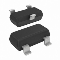
PMBD7000,215 NXP Semiconductors, PMBD7000,215 Datasheet - Page 3

PMBD7000,215
Manufacturer Part Number
PMBD7000,215
Description
DIODE SW DBL 100V 215MA HS SOT23
Manufacturer
NXP Semiconductors
Datasheet
1.PMBD7000215.pdf
(12 pages)
Specifications of PMBD7000,215
Package / Case
SOT-23-3, TO-236-3, Micro3™, SSD3, SST3
Voltage - Forward (vf) (max) @ If
1.25V @ 150mA
Current - Reverse Leakage @ Vr
500nA @ 100V
Current - Average Rectified (io) (per Diode)
215mA (DC)
Voltage - Dc Reverse (vr) (max)
100V
Reverse Recovery Time (trr)
4ns
Diode Type
Standard
Speed
Fast Recovery =< 500ns, > 200mA (Io)
Diode Configuration
1 Pair Series Connection
Mounting Type
Surface Mount
Product
Switching Diodes
Peak Reverse Voltage
100 V
Forward Continuous Current
0.215 A
Max Surge Current
4 A
Configuration
Dual Series
Recovery Time
4 ns
Forward Voltage Drop
1.1 V
Maximum Reverse Leakage Current
0.5 uA
Operating Temperature Range
+ 150 C
Maximum Operating Temperature
+ 150 C
Minimum Operating Temperature
- 65 C
Mounting Style
SMD/SMT
Rectifier Type
Switching Diode
Peak Rep Rev Volt
100V
Avg. Forward Curr (max)
0.215A
Rev Curr
0.5uA
Peak Non-repetitive Surge Current (max)
4A
Forward Voltage
1.1@0.1AV
Operating Temp Range
-65C to 150C
Package Type
TO-236AB
Rev Recov Time
4ns
Operating Temperature Classification
Military
Mounting
Surface Mount
Pin Count
3
Lead Free Status / RoHS Status
Lead free / RoHS Compliant
Lead Free Status / RoHS Status
Lead free / RoHS Compliant, Lead free / RoHS Compliant
Other names
568-1736-2
933859210215
PMBD7000 T/R
933859210215
PMBD7000 T/R
Available stocks
Company
Part Number
Manufacturer
Quantity
Price
Part Number:
PMBD7000,215
Manufacturer:
NEXPERIA/安世
Quantity:
20 000
NXP Semiconductors
5. Limiting values
6. Thermal characteristics
PMBD7000
Product data sheet
Table 5.
In accordance with the Absolute Maximum Rating System (IEC 60134).
[1]
[2]
[3]
[4]
Table 6.
[1]
[2]
Symbol
Per diode
V
V
I
I
I
P
Per device
T
T
T
Symbol
R
R
F
FRM
FSM
j
amb
stg
RRM
R
tot
th(j-a)
th(j-t)
Single diode loaded.
Double diode loaded.
T
Device mounted on an FR4 Printed-Circuit Board (PCB), single-sided copper, tin-plated and standard
footprint.
Single diode loaded.
Device mounted on an FR4 PCB, single-sided copper, tin-plated and standard footprint.
j
= 25 °C prior to surge.
Limiting values
Thermal characteristics
Parameter
repetitive peak reverse
voltage
reverse voltage
forward current
repetitive peak forward
current
non-repetitive peak
forward current
total power dissipation
junction temperature
ambient temperature
storage temperature
Parameter
thermal resistance from
junction to ambient
thermal resistance from
junction to tie-point
All information provided in this document is subject to legal disclaimers.
Rev. 4 — 16 September 2010
Conditions
square wave
T
amb
t
t
t
Conditions
in free air
p
p
p
= 1 μs
= 1 ms
= 1 s
≤ 25 °C
Double high-speed switching diode
[1][4]
[1][2]
[1]
[2]
[3]
Min
-
-
-
-
-
-
-
-
-
-
−55
−65
Min
-
-
PMBD7000
Typ
-
-
© NXP B.V. 2010. All rights reserved.
Max
100
100
215
125
450
4
1
0.5
250
150
+150
+150
Max
500
360
Unit
V
V
mA
mA
mA
A
A
A
mW
°C
°C
°C
Unit
K/W
K/W
3 of 12


