ACDC-620T Amprobe, ACDC-620T Datasheet - Page 53
ACDC-620T
Manufacturer Part Number
ACDC-620T
Description
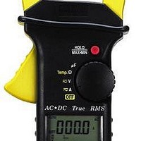
DMM CLAMP-ON TRMS
Manufacturer
Amprobe
Type
Digital (DMM)r
Datasheet
1.ACDC-620T.pdf
(65 pages)
Specifications of ACDC-620T
Includes
Battery, Case, Test Leads
Style
Clamp
Display Digits
4
Display Type
LCD, Bar Graph
Display Count
4000
Function
Voltage, Current, Resistance, Capacitance, Temperature
Functions, Extra
Continuity, Diode Test
Features
Auto Off, Hold, Min/Max/Ave, Sleep
Ranging
Auto/Manual
Response
True RMS
Frequency
45 Hz to 65 Hz
Maximum Ac Current
1 KA
True Rms
Yes
Voltage
400 V/100 V
Lead Free Status / RoHS Status
Contains lead / RoHS compliant by exemption
Other names
2730822


non-linear current. This generates odd harmonics of the 5OHz or 60Hz line
frequency. Therefore, the current waveform from the transformer could contain
not only a 60Hz component, but also a 180Hz component, a 30OHz compo-
nent, etc.
The vector addition in a properly balanced power distribution system feeding
non-linear loads may still be quite low. However, the vector addition does not
cancel all the harmonic currents. The odd multiples of the 3rd harmonic (called
the "TRIPLENS") are added together in the neutral. These harmonics can cre-
ate an RMS current in the transformers neutral wire that is 130( of the total
RMS current measured in any individual phase. For example, phase currents
of 80 amperes may cause 104 amperes of harmonic current in the neutral, the
most common harmonic being the 3rd. The electrical designer must consider
the following issues when designing a power distribution system that will con-
tain harmonic current.
1. The AC neutral wires must be of sufficient gauge to
2. The distribution transformer must have additional cooling to continue opera
3. Phase current harmonics are reflected to the primary winding and they
We can use this Meter to analyze components such as power distribution
transformers and power factor correction capacitors. An additional feature
allows the measurement of half-cycle peak current by using the 1 ms peak
hold feature. This allows the ability to determine crest factor:
This circulating harmonic current heats up the transformer.
allow for harmonic current.
tion at its rated capacity. This is because the harmonic current in the sec
ondary neutral wire is circulating in the deltaconnected primary winding.
continue back towards the power source, This can cause distortion of the
voltage wave so that any power factor correction capacitors on the line can
be easily overloaded.
NOTE: If Crest factor exceeds 1.1 harmonic distortion is present
Crest factor + Peak value/True rms value
52