ACDC-620T Amprobe, ACDC-620T Datasheet
ACDC-620T
Specifications of ACDC-620T


ACDC-620T Summary of contents
Page 1
... If the instrument still malfunctions, please call the phone number listed below: Service Division AMPROBE INSTRUMENT Miami, Florida 33150 Tel: 800-327-5060 outside the U.S.A. the local Amprobe representative will assist you. | AMPROBE DIVISION OF CORE INDUSTRIES INC. Miami, Florida 33150 Tel: 800-327-5060 Visit our Web-site HTTP://www.AMPROBE.COM ® ...
Page 2
... USER MANUAL AUNIQUE TRUE RMS CLAMP-ON MULTIMETER | ® AMPROBE Miramar, Florida 33025 Tel: 800-327-5060 Manual P/N: 978760 8/97 MODEL: ACDC-620T ® C LISTED ...
Page 3
... LIMITED WARRANTY Congratulations! You are now the owner of an AMPROBE quality crafted according to quality standards and contains quality components and workmanship. This instrument has been inspected for proper operation of all its functions. It has been tested by qualified factory technicians according to the long- established standards of AMPROBE ® ...
Page 4
CONTENTS LIMITED WARRANTY SAFETYINFORMATION AUNIQUE CLAMP-ON MULTIMETER INTRODUCTION USING THE METER SAFELY LCD DISPLAYILLUSTRATION GETTING ACQUAINTED WITH YOUR METER ALIGNMENTMARKS ROTARYSWITCH INPUTTERMINAL PUSH BOTTONS PUSH-BOTTONS OPERATIONS POWER ON OPTIONS SPECIALFUNCTIONS INSTRUCTIONS Dynamic Recording Data Hold Zero (Relative) Analog Bargraph Auto ...
Page 5
CONTENTS continued PAGE HOW TO OPERATE AC CURRENTMEASUREMENT DISTRIBUTION TRANSFORMER MEASUREMENT AC MOTOR CURRENTMEASUREMENT AC VOLTAGE MEASUREMENT RESSISTENCE / CONTINUITYMEASUREMENT TEMPERATURE MEASUREMENT CAPACITANCE MEASUREMENT ESPECIFICACIONES GENERALES GENERALSPECIFICATIONS ACCESSORIES AND REPLACEMENT PARTS CURENT HARMONICS THEORY TRUE RMS MEASUREMENT WAVE FORM COMPARISON ...
Page 6
SAFETYINFORMATION c SAFETYINFORMATION: To ensure that you use meter safely, follow the safety guidelines listed below. This meter is for indoor use, altitude up to 2000m. Avoid working alone. Take precautions when working around moving parts. Use the meter only ...
Page 7
Set the proper function and renge before attaching the metr to circuit. To avoid damaging the meter disconnect the test leads from test points before changing functions. Read this operation manual completly before using the meter and follow all safety ...
Page 8
AUNIQUE CLAMP-ON MULTIMETER c INTRODUCTION Measuring current accurately is difficult job in today's industrial plants and com- mercial buildings.An increasing number of personal computers, adjustable speed motor drivers, and other types of electronic equipment in short pulses and are reffered ...
Page 9
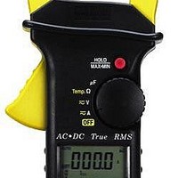
Start capacitor measurement Ohm measurement and k-type temperature Voltage measurement Current measurement 1ms Peak Hold for glitch capture Different Temperatures measurement Figure 1. AUnique Clamp-On Multimeter 7 Hand guard design for more safety. Dynamic Recording helps to record the variation ...
Page 10
USING THE METER SAFELY c WARNING Read " SAFETYINFORMATION" before using the meter.. c NOTE Some typical tests are provided in this manual. These tests are designed to help you understand how to use the Meter. Consult original manufacturer service ...
Page 11
LCD DISPLAYILLUSTRATION 1) - Negative polarity Annunciator 2) @OFF Auto Power Off Enabled Annunciator 3) q Low Battery Annunciator 4) DC Direct Current or Volytage Annunciator 5) AC Alterning Current or Volytage Annunciator 6) AUTO AUTOrange Mode Annunciator 7) DH ...
Page 12
Figure 2. LCD Display 11 ...
Page 13
Getting Acquainted WIth Your Meter c ALIGNMENT MARKS MARK Conductor Mark Figur3 3. Alignment Marks In order to meet the meeter accuracy spacifications when making a current meas- urement, the conductor must be inside the jaws and centered within the ...
Page 14
Rotary Switch To turn the meter on and select a function, turn the rotary switch (Figure switch setting. The whole display lights for one second. Then the meter is ready for use. (if you press and hold ...
Page 15
INPUT TERMINAL WARNING To avoid damaging the meter, do not exceed input limit shown below Table 1: ROTATORYSWITVH FUNCTION INPUTTRMINAL & COM AC 400 ~ 1000V(CATII) AC 400 ~ 600V(CATIII) DC 400 ~ 1000V(CATII) DC 400 ...
Page 16
Press to lselect DC.AC,DC+AC Press and hold for more than 1 second to toggle, between PEAK" and DC. Press to toggle 0 and Temperature measurements. 5. Press to toggle Continuity ON/OFF for Ohm measurement. Press to select T1-T2-T2 for ...
Page 17
Push-button Operations The operation of the push-buttons are outlined below. When a buton is pushed, an annunciator lights, and the unit beeps. turning the rotary switch to another switch setting resets all push buttons to thei default states. The pushbuttons ...
Page 18
Zero : Push this button momentarily to zero the residual current. Note: Allow the meter to stabilize before zeroing the display. The " " swill also be displayed continuity, Delta Temperature ) ) In ...
Page 19
POWER-ON OPTIONS c SELECTING POWER-ON OPTIONS Some options can only be selected when you turn the meter on. These power-on options are listed in Table 2. To select power-on press and hold the appriopriate pushbutton while turning the rotary switch ...
Page 20
SPECIALFUNCTIONS INSTRUCTIONS This clamp-on multimeter provides the operator with various functions including: c Dynamic Recording c Data Hold c Zero (Relative) c Analog bargraph c Auto Power Off and Sleep Mode c Disable Auto Power Off c Demonstrate Annunciator of ...
Page 21
The beeper sounds when a new maximun or minimum value is recorded overload is recorded the averaging function is stopped. An average value becomes "OL" (overloaded dynamic recording the auto powe off feature is ...
Page 22
Press for more than 1 second to enter Dynamic Recording Figure 7. Display of Dynamic Recording 21 ...
Page 23
DATAHOLD The data HOLD function allos operator to freeze the displayed digital value while the aanlog bargraph displays present readings. Press "DH" Hold button to enter the data Hold mode, and the "DH" annunciator is displayed. Press the button ...
Page 24
Figure 9. relative(Zero) Operation. c ANALOGBATRGRAPH The analog bargraph display provides a 12-segment analog reading representa tion. The unit of the bargraph is 100 counts/bar. 23 ...
Page 25
Figura 10. Analog Bar graph c AUTO POWER OFFAND SLEEPMODE There are two modes for power saving The instrument will enter the "sleep" mode within 15 minutes, unless: 1-1. Any push buttons have been pressed 1-2. The rotary ...
Page 26
Figure 11. Sleep Mode c DISABLE AUTO POWEROFF When the meter used for long periods of time you may want to disable the auto power off. Once the auto power off function is disabled, the meter ...
Page 27
Figure 12. Demostrate Annunciator. c CONTINUITY FUNCTION FOR OHMS MEASUREMENT To enable the continuity function, set the meter to the ) Press ) button momentarily to toggle the CONTINUITYfunction ON/OFF. ) The continuity range is 0-400.0 and the beeper will ...
Page 28
III IIII Figure 14. Continuity Operation c 1ms Peak Hold You can use this Meter to analyze components such as power distribution trans- formers and power factor correction capacitors. The additional features allow the measurement of ...
Page 29
If the reading is " OL", then you can push RANGE button momentarily to change measuring range and restart the PEAK+ measurement after setting the peak mode Press ) button to re-set the I ms peak hold ...
Page 30
HOW TO OPERATE c AC CURRENT MEASUREMENT WARNING: MAKE CERTAIN THATALLTESTLEADS ARE DISCONNECTED FROM THE METER TERMINALS Set the rotary switch to " A ". 2) Open the meter jaws and clamp around a single conductor. The most ...
Page 31
CORRECT INCORRECT Figure 17. Measuring AC Current. 30 ...
Page 32
DISTRIBUTION TRANSFORMER MEASUREMENT You can measure current, phase imbalance between phases, and true RMS neutral current. True RMS measurement yields the effective value. 1) Set the rotary switch to " A ". 2) Clamp around a phase wire of ...
Page 33
Figure 18. Measuring AC Curreft 32 ...
Page 34
AC MOTOR CURRENT MEASUREMENT You can measure starting (inrush) current , running current, and current imbal- ance in AC Motor circuits. Inrush current is typically 6-8 times the value of run- ning current, depending on the motor type.. 1. ...
Page 35
Figure 19. Measuring AC Motor Curent 34 ...
Page 36
AC VOLTAGE MEASUREMENT 1. Set the rotary switch to "V". 2. Insert the black test lead to "COM" terminal and red test lead to F " " terminal. 3. touch the probes to the test points and ...
Page 37
Figure 20. Measuring Voltage. 36 ...
Page 38
RESISTANCE / CONTINUITYMEASUREMENT CAUTION: Make sure that power is removed and all capacitors have been discharged before measuring. 1) Set the rotary switch to "TEMP. ". OLis displayed. 2) Insert the black test lead to "COM" terminal and red ...
Page 39
Figura 21. Measuring Resistance and Continuity. 38 FUSE CARTRIDGE ...
Page 40
... TEMPERATURE (K-TYPE) MEASUREMENTS The ACDC-620TLCD contains a dual display for Temperature Measurement. The larger digits display digits display o C (Celsius). Both readings are displayed simultaneously. CAUTION: Do not allow the temperature sensor to contact a surface which is ener- gized above 30 V RMS DC, such voltages pose a shock hazard. ...
Page 41
Press Shift Figure 22. Surface Temperature Measurement. 40 ...
Page 42
... Set the DKTA-620 selector switch to the "T1-T2" position Push the button on the ACDC-620Tmomentarily to enter the Differential Temperature Mode. The "TI-T2" and "A" annunciators will be displayed. 3) Read the displayed differential temperature. 4) For information on basic refrigeration theory refer to page 56. ...
Page 43
Contact where you want to measuring PRESS T Figure 23. Measuring Temperature on Refrigeration System. 42 ...
Page 44
CAPACITANCE MEASUREMENTS In many instances a motor can not be started due to a failed start/run capacitor. To test the capacitor: : Discharge the capacitor before testing Set the rotary switch to " F" position. 2) Insert ...
Page 45
Rojo Negro (+) (-) Figure 24. CAPACITANCEMEASUREMENTS. 44 ...
Page 46
GENERALSPECIFICATIONS Display: Display: Fully annunciated 4-digit liquid crystal display (LCD) with maximum reading of 4,000 count. Dual display in Temperature mode. 12 segments analog bar graph. Automatic polarity indication. Functions: DCV, ACV, DCA, ACA, OHM, Capacitance and Temperature. Measuring rate: ...
Page 47
MAX. Jaw Opening: To Accommodate Circuit Cables 2" diameter. Dimension (W) x 260 (L) mm 1.26"(H) x 2.52"(W) x 10.24"(L) Weight: 840 grams with battery included. (1.85 lbs with battery included.) Standard ...
Page 48
... Accessories and ReplacementsParts Amprobe P/N Description Safety Test Leads(included) DTL-3000 Carryimg Case(included) CC-ACDC 978760 Instruction Manual(included) MN-1604 9 Volt Alkaline Battery(included) DKTA-620 Dual input thermocouple adapter(opcional) TAC-DMM Single input thermocouple(opcional) TPK-56 Type K bead probe(opcional) 47 ...
Page 49
ELECTRICALSPECIFICATIONS Accuracy is giveN as ± reading + the number of least significant digits ± with relative hunidity Less than 80% R. VOLTAJE Range Resolution Accuracy 400V 0.1V ±(1% ...
Page 50
DC CURRENT Range Resolution 400A 0.1A 1000A CURRENT (TRUE RMS: From 10% al 100% of range) Range Resolution 45Hz~65Hz ±(2% rdg+5dgt) 400A 0.1A 1000A 1A ±(2.5% rdg + 5dgt) Crest Factor: <3:1 c CORRIENTE (RETENCIÓN DE ...
Page 51
K-TYPETEMPERATUREMEASUREMENTRANGE RANG Resolution Accuracy -40°C ~1372°C 1°C ±(0,5%rdg+3°C) -40°F ~ 2502°F 1°F ±(0,5%rdg+6°F) c TEMPERATURADIFERENCIALTIPO K Gama Resolución Precisión -50°C< T<100°C 1°C ±(0,5%rdg+3°F) -58°F< T<180°F 1°F ±(0,5%rdg+6°F) Note: Do not alow the temperature sensor to contact a surfece which ...
Page 52
CURRENT HARMONICS THEORY True-RMS current is very important because it directly relates to the amount of heat dissipated in wiring, transformers, and loads. Most clamp-on meters already in the field measure average current, not true RMS current, even if this ...
Page 53
This generates odd harmonics of the 5OHz or 60Hz line frequency. Therefore, the current waveform from the transformer could contain not only a 60Hz component, but also a 180Hz component, a 30OHz compo- nent, etc. The vector addition ...
Page 54
... TRUE RMS converters. The scale factor in these meters are adjusted so that they display the RMS value for a harmonic-free sine wave signal is not sinusoidal, average-responding meters do not display correct RMS readings. For a free video on Amprobe's Harmonalyzer, HA-2000 harmonic/waveform analyzer, please contact Amprobe directly. 53 ...
Page 55
WAVEFORMCOMPARISON e3. Illustrates the relationship between AC and DC components for common waveforms, and compares readings for TRUE RMS meters and average-responding meters. For example, consider the first waveform, a 1414V (zero-to-peak) sine wave. Both this ...
Page 56
Table 3. WAVEFORMCOMPARISONCHART * RMS CALIS THE DISPLAYED VALUEFOR AVERAGE RESPONDING METERS THATARE CALIBRATED RMS FOR SINE WAVES. 55 ...
Page 57
REFRIGERATIN THEORY Thermocouples are widely used in the process control and refrigeration industry. A review of basic refrigeration theory will help you to apply the meter in refrigeration applications. In any refrigeration application the goal is to transfer heat from ...
Page 58
EVAPORATOR COMPRESSORS FigurE 25. Refrigeration System. c The Refrigation Cycle Inside a refrigerator, a compressed gas in liquid form is released through an expan- sion valve into the low pressure of an evaporator. Here the liquefied gas evaporates (boils). The ...
Page 59
Once outside, the gas enters the compressor on the low-pressure side and is compressed compressed, the gas temperature rises above the surrounding air temperature. The hot gas dissipates its heat in the condenser, becoming liquid once again, ...
Page 60
Condenser Temperature The condenser's entire mid-section should be at the refrigerant's condensing tem- perature. The condensing temperature is related directly to the condenser's pres- sure, which is produced by the compressor's head-pressure. The condenser temperature varies with the system's load, ...
Page 61
Condenser Sub-cool Like the evaporator, the condenser is sized so that all the gas will be condensed before the last few coils, the liquid temperature drops slightly below the condensing temperature. In the case of an overloaded condenser or one ...
Page 62
MAINTENANCE WARNING To avoid electrical shock, do not perform any servicing unless you are qualified to do so. c SERVICE If the instrument fails to operate, check battery, test leads, etc. and replace as nec- essary. If the instrument still ...
Page 63
Pull up slightly Figure 26. step 1 of Battery replacement. 62 ...
Page 64
Pull and move to right. Figure 27. Step 2 of Battery Replacement. 63 ...
Page 65
CLEANING To clean the instrument, use s soft cloth dampened in a solution of mild detergent and water. Do not spery cleaner directly onto the instrument, since it may leak intothe cabinet and cause damage. Do not use chemicals ...