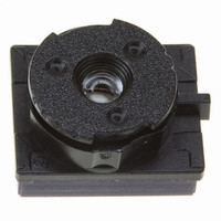
VS6502V015/T2 STMicroelectronics, VS6502V015/T2 Datasheet - Page 21

VS6502V015/T2
Manufacturer Part Number
VS6502V015/T2
Description
SENSOR COLOR VGA CMOS SMOP
Manufacturer
STMicroelectronics
Type
CMOS Imagingr
Datasheet
1.VS6502V015T2.pdf
(48 pages)
Specifications of VS6502V015/T2
Pixel Size
5.6µm x 5.6µm
Active Pixel Array
644H x 484V
Frames Per Second
30
Voltage - Supply
2.6 V ~ 3.6 V
Package / Case
SMOP2
Lead Free Status / RoHS Status
Lead free / RoHS Compliant
Other names
497-3884-1
Available stocks
Company
Part Number
Manufacturer
Quantity
Price
Part Number:
VS6502V015/T2
Manufacturer:
ST
Quantity:
20 000
VS6502
3.3
3.3.1
3.3.2
3.3.3
Types of messages
This section gives guidelines on the basic operations to read data from and write data to the serial
interface.
The serial interface supports variable length messages. A message may contain no data bytes, one
data byte or many data bytes. This data can be written to or read from common or different locations
within the sensor. The range of instructions available is detailed below.
Examples of these operations are given below. A full description of the internal registers is given in
Chapter
write address includes the read/write bit (the LSB) set to zero while this bit is set in the read
address.
Single location, single data write
When a single value is written to the sensor, the message looks as shown in
In this example, the register with index = 32 is set to 85. The index value is preserved in the sensor
and may be used by a subsequent read. The write message is terminated with a stop condition from
the master.
Single location, single data read
During a read sequence the sensor always sends the index used to get the first byte of data before
sending the data itself. The index can only be set by a write message.
No data write followed by same location read
When a location is to be read and the value of the stored index is not known, a write message with
no data byte must be written first in order to set the index. The read message then completes the
message sequence. To avoid relinquishing the serial to bus to another master, a repeated start
No data writes are used to set the index for a subsequent read message.
Multiple location writes may be used for fast information transfers.
4. For all examples, the slave address used is 0x20 for writing and 0x21 for reading. The
Start
Start
S
S
address
address
Device
Device
21
20
h
h
Figure 19: Single location, single write
Figure 20: Single location, single read
Ack
Ack
A
A
0
0
Index
Index
INDEX
32
h
A
A
Data
Data
DATA
85
h
A
A
Stop
Stop
Figure
Serial Control Bus
P
P
19.
21/48


