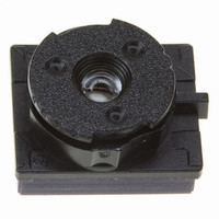
VS6502V015/T2 STMicroelectronics, VS6502V015/T2 Datasheet - Page 15

VS6502V015/T2
Manufacturer Part Number
VS6502V015/T2
Description
SENSOR COLOR VGA CMOS SMOP
Manufacturer
STMicroelectronics
Type
CMOS Imagingr
Datasheet
1.VS6502V015T2.pdf
(48 pages)
Specifications of VS6502V015/T2
Pixel Size
5.6µm x 5.6µm
Active Pixel Array
644H x 484V
Frames Per Second
30
Voltage - Supply
2.6 V ~ 3.6 V
Package / Case
SMOP2
Lead Free Status / RoHS Status
Lead free / RoHS Compliant
Other names
497-3884-1
Available stocks
Company
Part Number
Manufacturer
Quantity
Price
Part Number:
VS6502V015/T2
Manufacturer:
ST
Quantity:
20 000
VS6502
2.3.9
Note:
2.3.10 Exposure/gain control
Clock management and on-chip divider
The VS6502 has a built-in clock divider which acts on the input clock as shown in
clock divide ratio is controlled by register 37.
With the user programmable divider set to its default value of 1 (i.e. no divide), a 24 MHz input clock
will generate the frame and pixel rates shown in
The VS6502 can operate with a maximun external clock frequency of 27 MHz.
For values of clock divider other than 1, the rates shown above can be divided accordingly.
These rates are based on the default line and frame lengths. If the user increases either of these
then the frame rate will be reduced.
The sensor does not contain any form of automatic exposure or gain control. To produce a correctly
exposed image, exposure and gain values must be calculated externally and written to the sensor
via the serial interface. This function is handled by ST co-processors.
Exposure calculation
The exposure time for a pixel and the ADC range (therefore the gain) are programmable via the
serial interface. The explanation below assumes that the gain and exposure values are updated
together as part of a 5 byte serial interface auto-increment sequence.
Exposure time combines coarse, fine exposure, pixel rate also related to frame and line lengths, all
defined in
VGA
SSQVGA
WOIQVGA
Video Mode
Table
CLKIN
5.
Table 4: Default video frame rates
Figure 15: VS6502 clock divider
frame rate tuning
user programmable
divider (1/2/4/8/16)
CLKIN
(MHz)
24
24
24
Table
Frame rate
internal system clock
4.
(Hz)
30
60
60
Functional Description
Pixel rate
(MHz)
12
6
6
Figure 15.
The
15/48


