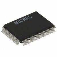
KSZ8893FQL-FX Micrel Inc, KSZ8893FQL-FX Datasheet - Page 10

KSZ8893FQL-FX
Manufacturer Part Number
KSZ8893FQL-FX
Description
2+1 Port 10/100 Switch W/Tranceivers & Frame Buffers, ( )
Manufacturer
Micrel Inc
Datasheet
1.KSZ8893FQL-FX.pdf
(117 pages)
Specifications of KSZ8893FQL-FX
Controller Type
Ethernet Switch Controller
Interface
MII, RMII, SNI
Voltage - Supply
3.1 V ~ 3.5 V
Operating Temperature
-40°C ~ 85°C
Mounting Type
Surface Mount
Package / Case
128-MQFP, 128-PQFP
Number Of Primary Switch Ports
3
Internal Memory Buffer Size
32
Operating Supply Voltage (typ)
3.3V
Fiber Support
Yes
Integrated Led Drivers
Yes
Power Supply Type
Analog/Digital
Package Type
PQFP
Vlan Support
Yes
Operating Temperature (max)
70C
Operating Temperature (min)
0C
Pin Count
128
Mounting
Surface Mount
Jtag Support
No
Operating Temperature Classification
Commercial
Data Rate
1000Mbps
Lead Free Status / RoHS Status
Lead free / RoHS Compliant
For Use With
576-1603 - EVAL KIT EXPERIMENTAL KSZ8893MQL
Current - Supply
-
Lead Free Status / RoHS Status
Compliant, Lead free / RoHS Compliant
Other names
576-3273
Available stocks
Company
Part Number
Manufacturer
Quantity
Price
Company:
Part Number:
KSZ8893FQL-FX
Manufacturer:
Micrel Inc
Quantity:
1 950
Company:
Part Number:
KSZ8893FQL-FX
Manufacturer:
FSC
Quantity:
1 800
Micrel, Inc.
KSZ8893FQL
List of Figures
Figure 1. TS-1000 OAM Frame Format ........................................................................................................................... 23
Figure 2. Typical TS-1000 Media Converter Application ................................................................................................. 24
Figure 3. KSZ8893FQL MC Loop Back Paths ................................................................................................................. 25
Figure 4. Typical Straight Cable Connection ................................................................................................................... 31
Figure 5. Typical Crossover Cable Connection ............................................................................................................... 31
Figure 6. Auto-Negotiation and Parallel Operation. ......................................................................................................... 32
Figure 7. Destination Address Lookup Flow Chart, Stage 1 ............................................................................................ 35
Figure 8. Destination Address Resolution Flow Chart, Stage 2....................................................................................... 36
Figure 9. 802.1p Priority Field Format.............................................................................................................................. 46
Figure 10. KSZ8893FQL EEPROM Configuration Timing Diagram. ............................................................................... 48
Figure 11. SPI Write Data Cycle. ..................................................................................................................................... 50
Figure 12. SPI Read Data Cycle. ..................................................................................................................................... 50
Figure 13. SPI Multiple Write. .......................................................................................................................................... 51
Figure 14. SPI Multiple Read. .......................................................................................................................................... 51
Figure 15. Far-End Loopback Path. ................................................................................................................................. 52
Figure 16. Near-end (Remote) Loopback Path................................................................................................................ 53
Figure 17. EEPROM Interface Input Timing Diagram.................................................................................................... 106
Figure 18. EEPROM Interface Output Timing Diagram ................................................................................................. 106
Figure 19. SNI Timing – Data Received from SNI ......................................................................................................... 107
Figure 20. SNI Timing – Data Input-to-SNI .................................................................................................................... 107
Figure 21. MII Timing – Data Received from MII ........................................................................................................... 108
Figure 22. MII Timing – Data Input-to-MII ...................................................................................................................... 108
Figure 23. RMII Timing – Data Received from RMII ...................................................................................................... 109
Figure 24. RMII Timing – Data Input-to-RMII................................................................................................................. 109
Figure 25. SPI Input Timing ........................................................................................................................................... 110
Figure 26. SPI Output Timing......................................................................................................................................... 111
Figure 27. Auto-Negotiation Timing ............................................................................................................................... 112
Figure 28. Reset Timing ................................................................................................................................................. 113
Figure 29. Recommended Reset Circuit ........................................................................................................................ 114
Figure 30. Recommended Reset Circuit for interfacing with CPU/FPGA Reset Output................................................ 114
10
October 2007
M9999-101607-1.3


