CY7C0853V-133BBC Cypress Semiconductor Corp, CY7C0853V-133BBC Datasheet - Page 14
CY7C0853V-133BBC
Manufacturer Part Number
CY7C0853V-133BBC
Description
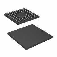
IC,SYNC SRAM,256KX36,CMOS,BGA,172PIN,PLASTIC
Manufacturer
Cypress Semiconductor Corp
Datasheets
1.CY7C0853V-133BBC.pdf
(29 pages)
2.CY7C0853V-133BBC.pdf
(33 pages)
3.CY7C0853V-133BBC.pdf
(29 pages)
Specifications of CY7C0853V-133BBC
Format - Memory
RAM
Memory Type
SRAM - Dual Port, Synchronous
Memory Size
9M (256K x 36)
Speed
133MHz
Interface
Parallel
Voltage - Supply
3.135 V ~ 3.465 V
Operating Temperature
0°C ~ 70°C
Package / Case
172-LFBGA
Lead Free Status / RoHS Status
Contains lead / RoHS non-compliant
Available stocks
Company
Part Number
Manufacturer
Quantity
Price
Company:

Part Number:
CY7C0853V-133BBC
Manufacturer:
Cypress Semiconductor Corp
Quantity:
10 000
Part Number:
CY7C0853V-133BBC
Manufacturer:
CYPRESS/赛普拉斯
Quantity:
20 000


Document #: 38-06059 Rev. *F
CLAMP
The optional CLAMP instruction allows the state of the signals
driven from CY7C0851V/CY7C0852V/CY7C0853V pins to be
determined from the boundary-scan register while the
BYPASS register is selected as the serial path between TDI
and TDO. CLAMP controls boundary cells to 1 or 0.
NBSRST
This is the Non-Boundary Scan Reset instruction. NBSRST
places the Bypass Register (BYR) between TDI and TDO
when selected. Its function is to reset every logic (similar to
MRST) except that it does not reset the JTAG logic.
Boundary Scan Cells (BSC)
Every CY7C0851V/CY7C0852V/CY7C0853V output has two
boundary scan cells; one for data, and one for three-state
Notes:
16. I
17. The “0”/”1” next to each state represents the value at TMS at the rising edge of CLK.
1
0
SB3
values only if JTAG pins are not active and mpdaster reset (MRST) not enabled.
RUN_TEST/
IDLE
TEST-LOGIC
RESET
0
1
Figure 3. TAP Controller State Diagram (FSM)
1
0
PRELIMINARY
SELECT
DR-SCAN
CAPTURE-DR
SHIFT-DR
EXIT1-DR
PAUSE-DR
EXIT2-DR
UPDATE-DR
1
0
1
0
1
1
0
[15]
CY7C0851V/CY7C0852V/CY7C0853V
control. JTAG TAP pins (TDI, TMS, TDO, TCK), MRST, and
all power and ground pins have no scan cell. Other
CY7C0851V/CY7C0852V/CY7C0853V inputs have only the
data scan cell.
Active and Standby Supply Current
When the instruction in the JTAG instruction register selects
the Boundary Scan Register (BSR) and the TAP controller is
in
RUN-TEST/IDLE, then the device supply current (I
I
both ports inactive with CMOS input levels, it is possible for the
supply current to exceed the ISB3 value given in the Electrical
Characteristics section of this data sheet.
SB1/2/3/4
0
any
) will increase. With the JTAG logic in this state, and
0
1
0
1
state
CY7C0831V/CY7C0832V
[17]
except
1
0
CAPTURE-IR
SHIFT-IR
EXIT1-IR
PAUSE-IR
EXIT2-IR
UPDATE-IR
SELECT
IR-SCAN
1
TEST-LOGIC-RESET
0
0
1
1
1
0
[16]
0
Page 14 of 33
1
0
1
0
CC
or
or
Related parts for CY7C0853V-133BBC
Image
Part Number
Description
Manufacturer
Datasheet
Request
R

Part Number:
Description:
CY7C0853V-133BBXI
Manufacturer:
Cypress Semiconductor Corp
Datasheet:
Part Number:
Description:
IC,SYNC SRAM,256KX36,CMOS,BGA,172PIN,PLASTIC
Manufacturer:
Cypress Semiconductor Corp
Datasheet:
Part Number:
Description:
IC,SYNC SRAM,256KX36,CMOS,BGA,172PIN,PLASTIC
Manufacturer:
Cypress Semiconductor Corp
Datasheet:

Part Number:
Description:
Manufacturer:
Cypress Semiconductor Corp
Datasheet:
Part Number:
Description:
Manufacturer:
Cypress Semiconductor Corp
Datasheet:
Part Number:
Description:
Manufacturer:
Cypress Semiconductor Corp
Datasheet:
Part Number:
Description:
Manufacturer:
Cypress Semiconductor Corp
Datasheet: