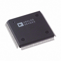
AD9887AKSZ-140 Analog Devices Inc, AD9887AKSZ-140 Datasheet - Page 27

AD9887AKSZ-140
Manufacturer Part Number
AD9887AKSZ-140
Description
IC,TV/VIDEO CIRCUIT,Video Digitizer,CMOS,QFP,160PIN,PLASTIC
Manufacturer
Analog Devices Inc
Datasheet
1.AD9887AKSZ-140.pdf
(52 pages)
Specifications of AD9887AKSZ-140
Applications
Graphic Cards, VGA Interfaces
Interface
Analog and Digital
Voltage - Supply
3.15 V ~ 3.45 V
Package / Case
160-MQFP, 160-PQFP
Mounting Type
Surface Mount
Lead Free Status / RoHS Status
Lead free / RoHS Compliant
Available stocks
Company
Part Number
Manufacturer
Quantity
Price
Company:
Part Number:
AD9887AKSZ-140
Manufacturer:
MAX
Quantity:
59
Company:
Part Number:
AD9887AKSZ-140
Manufacturer:
ADI
Quantity:
364
Company:
Part Number:
AD9887AKSZ-140
Manufacturer:
Analog Devices Inc
Quantity:
10 000
Part Number:
AD9887AKSZ-140
Manufacturer:
ADI/亚德诺
Quantity:
20 000
THEORY OF OPERATION—INTERFACE DETECTION
ACTIVE INTERFACE DETECTION AND SELECTION
For interface detection in the AD9887A, the system should
determine the correct interface and set the chip appropriately
through the serial bus. An external circuit should be used to
determine if the digital interface is active. A typical schematic
for this detection function is shown in Figure 28.
It is recommended that the system implement the interface
selection criteria, as described in Table 8. Because the digital
interface clock detect bit (0x11[4]) has been unreliable in some
applications, it is recommended that the active interface override
bit (0x12[7]) be set to 1. This allows the system to select the
interface through the serial bus register active interface select
(AIS) bit (0x12[6]). This selection should be based on the analog
interface detect obtained by OR’ing Bit 7, Bit 6, and Bit 5 of
Register 0x11 and on the digital interface detect obtained through
the external circuitry shown in Figure 28. When both interfaces
are active, priority must be determined by the system and the
appropriate interface must be selected via the AIS bit.
Table 8. Interface Selection and Power-Down Controls
Power-
Down
1
1
0
1
1
1
1
CLK+
CLK–
0.1µF
0.1µF
Figure 28. External Digital Interface Clock Detect Circuit
Active Interface
Override
(0x12[7])
1
1
X
1
1
1
1
11kΩ
10kΩ
3.3V
10kΩ
10kΩ
1
2
LT1715
+
–
9
5
10
6
Analog Interface
Detect (0x11[7],
0x11[6], or 0x11[5])
X
X
0
0
1
1
1
HIGH SPEED
COMPARATOR
8
1 = DVI CLOCK ACTIVE
0 = DVI CLOCK NOT ACTIVE
1.0µF
10kΩ
Digital Interface
Detect (from
External Circuit)
X
X
0
1
0
1
1
CLK
ACTIVE
Rev. B | Page 27 of 52
HOT-PLUG DETECT
In some HDCP-enabled applications it may be desirable to be
able to switch between the analog and DVI interfaces without
having an DVI plug/unplug event. In these applications, the circuit
in Figure 29 should be used for the hot-plug detect connection.
The FET switch should be controlled by the system-level software
to force an HPD event whenever the selected interface is switched
from the analog input to the DVI input.
POWER MANAGEMENT
The AD9887A is a dual-interface device with shared outputs.
Because only one interface can be used at a time, the unused
interface should be powered down. When the analog interface is
being used, most of the digital interface circuitry can be powered
down and vice versa. This helps to minimize the total power
dissipation of the AD9887A. In addition, if neither interface has
activity on it, both interfaces should be powered down.
The correct power-down state is set by selecting an interface to
be active through the serial bus when either or both interfaces
are active, and by setting the power-down register bit (0x12[0])
to 0 when neither interface has activity on it. In a given power
mode, not all circuitry in the inactive interface is powered down
completely. When the digital interface is active, Hsync detect
circuitry is not powered down. SOG, outputs, and the band gap
reference are powered up if either interface is active. The serial
bus stays active even if the entire chip is powered down.
AIS
0
1
X
1
0
0
1
Active
Interface
Analog
Digital
None
Digital
Analog
Analog
Digital
Figure 29. Manual Hot-Plug Detect
HPD
+5V
Description
Force the analog interface active.
Force the digital interface active.
Neither interface is detected. Both
interfaces are powered down and
the S
The digital interface is detected.
Power down the analog interface.
The analog interface is detected.
Power down the digital interface.
Both interfaces are detected. The
analog interface has priority.
Both interfaces are detected. The
digital interface has priority.
14
15
HPD CONTROL BIT
CDT
pin is set to Logic 0.
1kΩ
AD9887A


