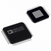
AD9775BSVZ Analog Devices Inc, AD9775BSVZ Datasheet - Page 32

AD9775BSVZ
Manufacturer Part Number
AD9775BSVZ
Description
IC,D/A CONVERTER,DUAL,14-BIT,CMOS,TQFP,80PIN
Manufacturer
Analog Devices Inc
Series
TxDAC+®r
Datasheet
1.AD9775BSVZRL.pdf
(56 pages)
Specifications of AD9775BSVZ
Settling Time
11ns
Number Of Bits
14
Data Interface
Parallel
Number Of Converters
2
Voltage Supply Source
Analog and Digital
Power Dissipation (max)
410mW
Operating Temperature
-40°C ~ 85°C
Mounting Type
Surface Mount
Package / Case
80-TQFP Exposed Pad, 80-eTQFP, 80-HTQFP, 80-VQFP
Number Of Channels
2
Resolution
14b
Interface Type
Parallel
Single Supply Voltage (typ)
3.3V
Dual Supply Voltage (typ)
Not RequiredV
Architecture
R-2R
Power Supply Requirement
Analog and Digital
Output Type
Current
Single Supply Voltage (min)
3.1V
Single Supply Voltage (max)
3.5V
Dual Supply Voltage (min)
Not RequiredV
Dual Supply Voltage (max)
Not RequiredV
Operating Temp Range
-40C to 85C
Operating Temperature Classification
Industrial
Mounting
Surface Mount
Pin Count
80
Lead Free Status / RoHS Status
Lead free / RoHS Compliant
For Use With
AD9775-EBZ - BOARD EVALUATION FOR AD9775
Lead Free Status / Rohs Status
Compliant
Available stocks
Company
Part Number
Manufacturer
Quantity
Price
Company:
Part Number:
AD9775BSVZ
Manufacturer:
Analog Devices Inc
Quantity:
135
Company:
Part Number:
AD9775BSVZ
Manufacturer:
Analog Devices Inc
Quantity:
10 000
Part Number:
AD9775BSVZ
Manufacturer:
ADI/亚德诺
Quantity:
20 000
Company:
Part Number:
AD9775BSVZRL
Manufacturer:
Analog Devices Inc
Quantity:
10 000
AD9775
MODULATION, NO INTERPOLATION
With Control Register 0x01, Bit 7 and Bit 6 set to 00, the
interpolation function on the AD9775 is disabled. Figure 59
through Figure 62 show the DAC output spectral characteristics
of the AD9775 in the various modulation modes, all with the
interpolation filters disabled. The modulation frequency is
determined by the state of Control Register 0x01, Bit 5 and Bit 4.
The tall rectangles represent the digital domain spectrum of a
baseband signal of narrow bandwidth. By comparing the digital
The Effects of the Digital Modulation on the DAC Output Spectrum, Interpolation Disabled
–100
–100
–20
–40
–60
–80
–20
–40
–60
–80
0
0
0
0
Figure 59. No Interpolation, Modulation Disabled
Figure 60. No Interpolation, Modulation = f
0.2
0.2
0.4
0.4
f
f
OUT
OUT
( ×
( ×
f
f
DATA
DATA
0.6
0.6
)
)
0.8
0.8
DAC
/2
1.0
1.0
Rev. E | Page 32 of 56
domain spectrum to the DAC sin(x)/x roll-off, an estimate can
be made for the characteristics required for the DAC recon-
struction filter.
Note also, per the previous discussion on amplitude
modulation, that the spectral components (where modulation is
set to f
where the modulation is f
components add constructively, and there is no
scaling effect.
–100
–100
–20
–40
–60
–80
–20
–40
–60
–80
0
0
S
/4 or f
0
0
Figure 61. No Interpolation, Modulation = f
Figure 62. No Interpolation, Modulation = f
S
/8) are scaled by a factor of 2. In the situation
0.2
0.2
S
0.4
0.4
/2, the modulated spectral
f
f
OUT
OUT
( ×
( ×
f
f
DATA
DATA
0.6
0.6
)
)
0.8
0.8
DAC
DAC
/4
/8
1.0
1.0


