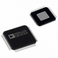
AD9775BSVZ Analog Devices Inc, AD9775BSVZ Datasheet - Page 2

AD9775BSVZ
Manufacturer Part Number
AD9775BSVZ
Description
IC,D/A CONVERTER,DUAL,14-BIT,CMOS,TQFP,80PIN
Manufacturer
Analog Devices Inc
Series
TxDAC+®r
Datasheet
1.AD9775BSVZRL.pdf
(56 pages)
Specifications of AD9775BSVZ
Settling Time
11ns
Number Of Bits
14
Data Interface
Parallel
Number Of Converters
2
Voltage Supply Source
Analog and Digital
Power Dissipation (max)
410mW
Operating Temperature
-40°C ~ 85°C
Mounting Type
Surface Mount
Package / Case
80-TQFP Exposed Pad, 80-eTQFP, 80-HTQFP, 80-VQFP
Number Of Channels
2
Resolution
14b
Interface Type
Parallel
Single Supply Voltage (typ)
3.3V
Dual Supply Voltage (typ)
Not RequiredV
Architecture
R-2R
Power Supply Requirement
Analog and Digital
Output Type
Current
Single Supply Voltage (min)
3.1V
Single Supply Voltage (max)
3.5V
Dual Supply Voltage (min)
Not RequiredV
Dual Supply Voltage (max)
Not RequiredV
Operating Temp Range
-40C to 85C
Operating Temperature Classification
Industrial
Mounting
Surface Mount
Pin Count
80
Lead Free Status / RoHS Status
Lead free / RoHS Compliant
For Use With
AD9775-EBZ - BOARD EVALUATION FOR AD9775
Lead Free Status / Rohs Status
Compliant
Available stocks
Company
Part Number
Manufacturer
Quantity
Price
Company:
Part Number:
AD9775BSVZ
Manufacturer:
Analog Devices Inc
Quantity:
135
Company:
Part Number:
AD9775BSVZ
Manufacturer:
Analog Devices Inc
Quantity:
10 000
Part Number:
AD9775BSVZ
Manufacturer:
ADI/亚德诺
Quantity:
20 000
Company:
Part Number:
AD9775BSVZRL
Manufacturer:
Analog Devices Inc
Quantity:
10 000
AD9775
TABLE OF CONTENTS
Features .............................................................................................. 1
Applications....................................................................................... 1
Functional Block Diagram .............................................................. 1
Revision History ............................................................................... 3
General Description ......................................................................... 4
Specifications..................................................................................... 5
Absolute Maximum Ratings............................................................ 9
Pin Configuration and Function Descriptions........................... 10
Typical Performance Characteristics ........................................... 12
Terminology .................................................................................... 17
Mode Control (via SPI Port) ......................................................... 18
Register Descriptions ..................................................................... 19
Functional Description .................................................................. 21
Product Highlights ....................................................................... 4
DC Specifications ......................................................................... 5
Dynamic Specifications ............................................................... 6
Digital Specifications ................................................................... 7
Digital Filter Specifications ......................................................... 8
ESD Caution.................................................................................. 9
Thermal Resistance ...................................................................... 9
Address 0x00 ............................................................................... 19
Address 0x01 ............................................................................... 19
Address 0x02 ............................................................................... 19
Address 0x03 ............................................................................... 20
Address 0x04 ............................................................................... 20
Address 0x05, Address 0x09 ..................................................... 20
Address 0x06, Address 0x0A..................................................... 20
Address 0x07, Address 0x0B ..................................................... 20
Address 0x08, Address 0x0C..................................................... 20
Address 0x08, Address 0x0C..................................................... 20
Serial Interface for Register Control ........................................ 21
General Operation of the Serial Interface ............................... 21
Instruction Byte .......................................................................... 22
Serial Interface Port Pin Descriptions ..................................... 22
MSB/LSB Transfers..................................................................... 22
Notes on Serial Port Operation ................................................ 22
DAC Operation........................................................................... 24
Rev. E | Page 2 of 56
Applying the Output Configurations........................................... 42
Evaluation Board ............................................................................ 44
Outline Dimensions ....................................................................... 54
1R/2R Mode ................................................................................ 25
Clock Input Configurations...................................................... 25
Programmable PLL .................................................................... 26
Power Dissipation....................................................................... 27
Sleep/Power-Down Modes........................................................ 28
Two-Port Data Input Mode ...................................................... 28
PLL Enabled, Two-Port Mode .................................................. 28
DATACLK Inversion.................................................................. 29
DATACLK Driver Strength....................................................... 29
PLL Enabled, One-Port Mode .................................................. 29
ONEPORTCLK Inversion......................................................... 29
ONEPORTCLK Driver Strength.............................................. 30
IQ Pairing .................................................................................... 30
PLL Disabled, Two-Port Mode................................................. 30
PLL Disabled, One-Port Mode ................................................. 30
Digital Filter Modes ................................................................... 31
Amplitude Modulation.............................................................. 31
Modulation, No Interpolation .................................................. 32
Modulation, Interpolation = 2× ............................................... 33
Modulation, Interpolation = 4× ............................................... 34
Modulation, Interpolation = 8× ............................................... 35
Zero Stuffing ............................................................................... 36
Interpolating (Complex Mix Mode)........................................ 36
Operations on Complex Signals............................................... 36
Complex Modulation and Image Rejection of Baseband
Signals .......................................................................................... 37
Image Rejection and Sideband Suppression of Modulated
Carriers ........................................................................................ 38
Unbuffered Differential Output, Equivalent Circuit ............. 42
Differential Coupling Using a Transformer............................ 42
Differential Coupling Using an Op Amp................................ 43
Interfacing the AD9775 with the AD8345 Quadrature
Modulator.................................................................................... 43
Ordering Guide .......................................................................... 54


