205606-3 TE Connectivity, 205606-3 Datasheet - Page 81
205606-3
Manufacturer Part Number
205606-3
Description
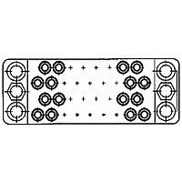
15 POS. SOC. BLOCK
Manufacturer
TE Connectivity
Type
Housingr
Datasheet
1.205606-3.pdf
(95 pages)
Specifications of 205606-3
Number Of Contacts
15POS
Number Of Contact Rows
3
Body Orientation
Straight
Pitch (mm)
5.08mm
Gender
RCP
Housing Material
Phenolic
Housing Color
Black
Product Length (mm)
41.4mm
Rohs Compliant
YES
Product Type
Housing
Type Of Connector
Posted
Mount
Panel
Mounting Hardware
None
High Voltage
No
Number Of Positions
15
Preloaded Contacts
No
Center Fastener
No
Connector Style
Receptacle
Rohs/elv Compliance
RoHS compliant, ELV compliant
Lead Free Solder Processes
Wave solder capable to 240°C, Wave solder capable to 260°C, Wave solder capable to 265°C
Rohs/elv Compliance History
Always was RoHS compliant
Lead Free Status / RoHS Status
Compliant


Sub Head
Guide Pins and Sockets
Sub-Sub Head
Material and Finish
Housing—
Guide Pins and Sockets—Stainless
steel
Contact—
Lockwashers—Stainless steel
Hex Nuts—Steel, zinc plated
Sub-Sub Head
Housing—
Contact—
Guiding hardware is used
to align connector halves
during mating. This hardware
can also be used for keying
connectors to provide for
proper mating. Guiding hard-
ware can be readily secured
to connector housings using
the Nut Driver Tool shown
b e l o w .
Center Guide Pins and
Sockets are used primarily
in housings having a single
mounting hole, but can also
be used in the centermost
hole of housings having 3
or 4 mounting holes.
Corner Guide Pins and
Sockets are used in the cor-
ner holes of housings having
2, 3 or 4 mounting holes.
They cannot be used in cen-
ter mounting holes which are
slightly deeper than corner
mounting holes to accept
J a c k s c r e w s .
Dimensions are shown for reference
purposes only.
Part No. 811262-1 (4-40)
Part No. 811262-2 (6-32)
Nut Driver
M Series
Pin and Socket Connectors
Heading
Guiding Hardware
1
2
3
**These Corner or Center Guide Sockets (.880 [22.35] long) are to be used when housings are loaded with
* *Corner Socket, Part No. 204099-2 (.838 [21.29] long), is to be used when housings are loaded with Subminiature
Dimensions are in inches and mil-
limeters unless otherwise specified.
Values in brackets are metric equiva-
lents.
Two Long Pins are to be installed in diagonal corners. Use without Guide Sockets.
Hex Nut Stainless Steel.
Without Spacer.
Subminiature COAXICON contacts.
C O A X I C O Nc o n t a c t s .
Corner Socket
Corner Socket
Corner Socket
Center Socket
Center Pin
Corner Pin
Corner Pin
Corner Pin
Long Pin
Guide Pins and Sockets
Washer
Type
Lock
Hex Nut
Pin
Spacer
4-40
Pin
[21.34]
.840
1
Center Guide
Washer
Lock
Hex Nut
[27.86]
1.097
6-32
200389-2
200390-2
207619-1*
200833-2
200835-2
203964-1*
201046-2
201047-2
203966-1*
202173-5
202173-1
202174-1
202174-4
204099-2**
201540-1
Part No.
Washer
Lock
Hex Nut
3
3
Socket
2
4-40
75, 104 and 160 CF 75, 104 and 160 CF
41, 50, 75 and 104
[19.81]
6, 14, 20, 26, 34,
.780
Spacer
Specifications subject to change.
34 and 50
Standard
104 CF
Washer
Socket
Lock
Corner Guide (104 CF)
Hex Nut
6-32
[15.88]
.625**
Connectors Used On (No. of Positions)
41, 50, 75 and 104
(34 & 50 Pos.)
6, 14, 20, 26, 34,
Washer
(75, 104, 160CF Pos.)
Lock
Hex Nut
34 and 50
4-40
Posted
104 CF
Pin
Hex Nut
6-32
[21.08]
.830
Corner Guide
Washer
Lock
Current
Long Pin
Technical Support Center
1-800-522-6752
www.tycoelectronics.com
High
Hex Nut
12
12
—
—
6-32
[29.36]
1.156
Special Application
(34 & 50 Pos.)
Washer
Lock
Hex Nut
15, 16 and 42 20 and 28
4-40
Socket
16 and 42
Mixed
[20.19]
(75, 104, 160CF Pos.)
29
.795*
—
Catalog 82003
Hex Nut
Revised 3-01
6-32
Voltage
High
20
28
—
81
Related parts for 205606-3
Image
Part Number
Description
Manufacturer
Datasheet
Request
R

Part Number:
Description:
Printers THERMAL PRINTER HS-SLEEVE MARKER
Manufacturer:
TE Connectivity


Part Number:
Description:
High Speed / Modular Connectors 30P HEADER ASSY
Manufacturer:
TE Connectivity
Datasheet:

Part Number:
Description:
High Speed / Modular Connectors REC 6X005P R/A LT B-PLANE HS3
Manufacturer:
TE Connectivity
Datasheet:

Part Number:
Description:
High Speed / Modular Connectors 2MM HM RCPT 50P R/A AU
Manufacturer:
TE Connectivity
Datasheet:

Part Number:
Description:
High Speed / Modular Connectors 2MM HM RCPT 50P R/A AU
Manufacturer:
TE Connectivity
Datasheet:


Part Number:
Description:
Manufacturer:
TE Connectivity
Datasheet:


Part Number:
Description:
Manufacturer:
TE Connectivity
Datasheet:

Part Number:
Description:
Manufacturer:
TE Connectivity
Datasheet:

Part Number:
Description:
Manufacturer:
TE Connectivity
Datasheet: