205606-3 TE Connectivity, 205606-3 Datasheet - Page 31
205606-3
Manufacturer Part Number
205606-3
Description
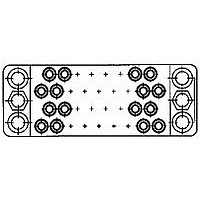
15 POS. SOC. BLOCK
Manufacturer
TE Connectivity
Type
Housingr
Datasheet
1.205606-3.pdf
(95 pages)
Specifications of 205606-3
Number Of Contacts
15POS
Number Of Contact Rows
3
Body Orientation
Straight
Pitch (mm)
5.08mm
Gender
RCP
Housing Material
Phenolic
Housing Color
Black
Product Length (mm)
41.4mm
Rohs Compliant
YES
Product Type
Housing
Type Of Connector
Posted
Mount
Panel
Mounting Hardware
None
High Voltage
No
Number Of Positions
15
Preloaded Contacts
No
Center Fastener
No
Connector Style
Receptacle
Rohs/elv Compliance
RoHS compliant, ELV compliant
Lead Free Solder Processes
Wave solder capable to 240°C, Wave solder capable to 260°C, Wave solder capable to 265°C
Rohs/elv Compliance History
Always was RoHS compliant
Lead Free Status / RoHS Status
Compliant


Type III+, Crimp, Snap-In
Material
Contact Body—Brass or phosphor bronze
Retention Spring—Stainless steel
Finish
See chart.
Contact Size 16—Pin Diameter .062 [1.57] (Test Current, 13 Ampere)‡
Dimensions are shown for reference
purposes only.
1
2
3
4
5
Overall insulation crimp diameter, including crimp barrel,
must not exceed .125 [3.18].
.000015 [0.00038] gold in the mating area over .000050
[0.00127] min. nickel.
.000030 [0.00076] gold in the mating area, with gold flash
on remainder, over .000050 [0.00127] min. nickel.
.000030 [0.00076] gold in the mating area, with gold gradi-
ent on remainder, over .000050 [0.00127] min. nickel.
Contacts can only be used in Metrimate, Series 1 (Arr. 23-
24), Series 4 (Arr. 23-13M, 23-16M, 23-22M), and VDE
connectors.
AWG
30-28
30-26
26-24
24-20
18-16
18-14
Wire Size
Range
0.05-0.09
0.05-0.15
0.12-0.2
0.2-0.6
0.8-1.4
0.8-2.0
Pin
mm
Socket
2
.040-.060
.014-.030
.035-.055
.040-.080
.060-.120
.080-.100
.080-.100
.080-.100
.110-.150
.015-.030
0.38-0.76
1.02-1.52
0.36-0.76
0.89-1.40
1.02-2.03
1.52-3.05
2.03-2.54
2.03-2.54
2.03-2.54
2.79-3.81
Range
Dia.
Ins.
M Series
Pin and Socket Connectors
Signal Contacts
1
1
1
1
5
1
1
1
5
Dimensions are in inches and mil-
limeters unless otherwise specified.
Values in brackets are metric equiva-
lents.
[
[
1.588
.0625
+0.025
–0.051
+.0010
–.0020
Sel. Gold/Nickel
Sel. Gold/Nickel
Sel. Gold/Nickel
Sel. Gold/Nickel
Sel. Gold/Nickel
Sel. Gold/Nickel
Sel. Gold/Nickel
Sel. Gold/Nickel
Sel. Gold/Nickel
Sel. Gold/Nickel
Sel. Gold/Nickel
Sel. Gold/Nickel
Sel. Gold/Nickel
Sel. Gold/Nickel
Sel. Gold/Nickel
Sel. Gold/Nickel
Bright Tin-Lead
Bright Tin-Lead
Bright Tin-Lead
Bright Tin-Lead
Bright Tin-Lead
Bright Tin-Lead
Bright Tin-Lead
Bright Tin-Lead
[9.91]
Gold/Nickel
Gold/Nickel
Gold/Nickel
Gold/Nickel
Gold/Nickel
Gold/Nickel
Gold/Nickel
Gold/Nickel
.390
]
Contact
Dia.
Related Product Data
Application Tooling—Pages 90, 91
Technical Documents
114-10004 Application Specification
108-10042 Product Specification
Finish
6
S
*Commercial PRO-CRIMPER II hand tool for field repair
To use with the 626 Pneumatic Tool System: remove the
crimping head from the Straight Action Hand Tool (SAHT)
Assembly, order SAHT Adapter Part No. 217201-1, Adapter
Holder Part No. 356304-1 (with ratchet) or 189928-1 (with-
out), and Power Unit PartNo. 189721-1 (hand actuated) or
189722-1 (foot actuated).
only. Note: Die Set can be adapted for use with the 626
Pneumatic Tool System.
Standard reeling of strip form contacts.
Min.
Pin Body
2
2
2
2
2
2
2
2
3
3
3
3
4
3
4
3
4
3
4
3
4
3
4
3
(Continued)
2-66102-2
1-66359-1
1-66359-0
1-66359-2
788085-3
788085-1
66098-2
66425-6
66425-7
66425-8
66393-7
66393-8
66106-6
66106-7
66106-8
66102-7
66102-8
66102-9
66564-6
66564-8
66564-1
66332-5
66332-7
66332-8
66098-7
66098-8
66098-9
66098-6
66359-6
66359-9
66597-1
66597-2
Pin
Spring, Stainless Steel
—
—
—
—
Pin
Contact No.
Strip Form
S
Specifications subject to change.
2-66104-5
2-66104-3
1-66358-2
1-66358-4
1-66358-0
1-66358-3
788088-2
788088-1
66424-6
66424-7
66424-8
66394-7
66394-8
66108-6
66108-7
66108-8
66108-1
66104-7
66104-8
66104-9
66104-1
66563-6
66563-8
66331-5
66331-7
66331-8
66331-2
66100-7
66100-8
66100-9
66358-6
66358-9
66358-1
66598-1
66598-7
66598-2
Socket
—
—
1-66103-2
788085-4
66429-3
66429-4
66406-4
66107-2
66107-3
66107-4
66103-2
66103-3
66103-4
66566-2
66566-4
66566-1
66400-1
66400-3
66400-4
66099-2
66099-3
66099-4
66099-1
66361-2
66361-7
66361-3
66361-4
66361-8
66602-1
66602-2
Pin
—
—
—
—
—
—
—
Loose Piece
Contact No.
‡Single contact, free-air test current is not to be construed
Insertion Tool Part No. 91002-1 (for insulation diameters
.070 [1.78] or less), No. 200893-2 (for insulation diameters
.090 [2.29] max.).
Extraction Tool Part No. 305183.
(Instruction Sheet 408-1216)
***Call the Technical Support Center at 1-800-522-6752 for
as contact rating current. Use only for testing. Refer to
contact current carrying capability information on page 7.
Ferrule, Brass,
1-66105-3
Automatic Machine Applicator Part Numbers.
Nickel Flash
788088-3
66428-3
66428-4
66405-4
66109-2
66109-3
66109-4
66109-1
66105-2
66105-3
66105-4
66105-1
66565-2
66565-4
66399-1
66399-3
66399-4
66399-2
66101-2
66101-3
66101-4
66360-2
66360-7
66360-3
66360-4
66360-8
66360-1
66601-1
66601-2
Socket
Stainless Steel
—
—
—
—
—
—
[2.87]
Spring,
.113
[13.46
.530
Max.
Dia.
±.010
Technical Support Center
1-800-522-6752
www.tycoelectronics.com
±0.25
]
Loose Piece
Socket
Hand Tool
90716-1
90066-7
90225-2
90066-7
58495-1*
90066-7
58495-1*
90331-1
90067-5
90225-2
90067-4
90067-5
58495-1*
90310-3
90310-2
or
or
or
Tooling Part No.
6
6
6
6
6
6
6
6
6
6
6
or
or
Catalog 82003
or 567947-1***
or 680602- ***
or 466979-1***
or 567363- ***
567867-1***
466598- ***
466585-3***
466321- ***
466908-2***
466323- ***
466907-2***
466383-4***
466324- ***
466942-1***
466325- ***
466906-1***
466326- ***
466923-2***
466958-1***
567364- ***
A p p l i c a t o r s
Strip Form
Revised 3-01
or
or
or
or
or
or
31
Related parts for 205606-3
Image
Part Number
Description
Manufacturer
Datasheet
Request
R

Part Number:
Description:
Printers THERMAL PRINTER HS-SLEEVE MARKER
Manufacturer:
TE Connectivity


Part Number:
Description:
High Speed / Modular Connectors 30P HEADER ASSY
Manufacturer:
TE Connectivity
Datasheet:

Part Number:
Description:
High Speed / Modular Connectors REC 6X005P R/A LT B-PLANE HS3
Manufacturer:
TE Connectivity
Datasheet:

Part Number:
Description:
High Speed / Modular Connectors 2MM HM RCPT 50P R/A AU
Manufacturer:
TE Connectivity
Datasheet:

Part Number:
Description:
High Speed / Modular Connectors 2MM HM RCPT 50P R/A AU
Manufacturer:
TE Connectivity
Datasheet:


Part Number:
Description:
Manufacturer:
TE Connectivity
Datasheet:


Part Number:
Description:
Manufacturer:
TE Connectivity
Datasheet:

Part Number:
Description:
Manufacturer:
TE Connectivity
Datasheet:

Part Number:
Description:
Manufacturer:
TE Connectivity
Datasheet: