205606-3 TE Connectivity, 205606-3 Datasheet - Page 8
205606-3
Manufacturer Part Number
205606-3
Description
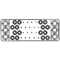
15 POS. SOC. BLOCK
Manufacturer
TE Connectivity
Type
Housingr
Datasheet
1.205606-3.pdf
(95 pages)
Specifications of 205606-3
Number Of Contacts
15POS
Number Of Contact Rows
3
Body Orientation
Straight
Pitch (mm)
5.08mm
Gender
RCP
Housing Material
Phenolic
Housing Color
Black
Product Length (mm)
41.4mm
Rohs Compliant
YES
Product Type
Housing
Type Of Connector
Posted
Mount
Panel
Mounting Hardware
None
High Voltage
No
Number Of Positions
15
Preloaded Contacts
No
Center Fastener
No
Connector Style
Receptacle
Rohs/elv Compliance
RoHS compliant, ELV compliant
Lead Free Solder Processes
Wave solder capable to 240°C, Wave solder capable to 260°C, Wave solder capable to 265°C
Rohs/elv Compliance History
Always was RoHS compliant
Lead Free Status / RoHS Status
Compliant


8
The presentation of current-
carrying capacity in AMP
product specifications includes
two parts:
Practical Values
The current-rating method
gives designers practical
values applicable to their appli-
cations. While the specified
current levels for a contact may
be lower than for other testing
methods, they are more realis-
tic and simplify the system
design process.
“Spec-manship” is replaced
by a realistic assessment of the
current-carrying capacity of a
Connector/Contact
Acceptability
As previously stated, choosing
the appropriate connector/con-
tact combination is fundamental
to the successful function of all
connectors. The Selection Chart,
shown at right, is designed to
simplify your choice of connec-
tors and their acceptable
contacts. Once you have
selected the wire size, current-
carrying capacity need, number
of positions required, and the
type of contacts needed in your
choice of connector, refer to this
matrix for a quick look at exactly
what is acceptable in a given
connector type.
Dimensions are shown for reference
purposes only.
First, a base curve showing
current levels versus T-rise for
a single circuit and the largest
wire size (See figure 1). This
represents the maximum cur-
rent capacity of the contact.
The curve is usually flat up to
75°C ambient and then drops
off. Up to 75°C, the 30°C
T-rise limits the amount of
current, and above 75°C the
current must be reduced to
keep the combination of
ambient temperature and
T-rise from exceeding the
maximum operating tempera-
ture of 105°C.
Next are rating factors; a
table of multipliers to account
for connector loading and for
smaller wire sizes (See figure 2).
The designer first determines
the base current for the
ambient conditions of the
application; then multiplies
this base current by the rating
factors to find the current
level for the application’s
loading factor and wire size.
Contact Selection Chart
M Series
Pin and Socket Connectors
Note: Data is not typical of a
specific M Series connector
configuration. For specific
current rating information
based on % connector loading,
contact Tyco Electronics.
To demonstrate the method of
specifying current, consider the
following application conditions;
an ambient temperature of 65°C,
a 50% loading of contacts in
the housing, and 20 AWG
[0.6mm
contact under varying condi-
tions of temperature, connector
loading, and wire size.
Specific current-carrying data
based on EOL and % loading
is available from Tyco
Electronics Corporation.
Please contact your local Sales
Engineer or call Tyco
Electronics Corporation.
Presentation—Example of New Current Rating Format
Dimensions are in inches and mil-
limeters unless otherwise specified.
Values in brackets are metric equiva-
lents.
Connector
From Figure 1, the base cur-
rent rating is 14 ampere with
18 AWG [0.8mm
Figure 2, the rating factor for
50% loading and 20 AWG
[0.6mm
The specific rating for this appli-
c a t i o n is the product of the
base rating and the rating factor:
Each of the contacts can
carry 9.5 ampere.
However, if the ambient tem-
perature is 80°C the allowable
T-rise becomes 25°C. The base
current must be lowered to
12.8 ampere so that the 105°C
maximum operating tempera-
ture is not exceeded. The
current rating then becomes:
M Series
M Series
Special
Type
12.8 x 0.68 = 8.7 a m p e r e .
14 x 0.68 = 9.5 ampere
2
] wire.
2
] wire is 0.68.
Type I
Type II
2
] wire.
High Current
Type II/III+
Graph shows the relationship between base current, ambient
temperature, and contact T-rise.
Rating factors allow the base current to be adjusted for various
connector loading and wire sizes.
Type III+
Specifications subject to change.
Type III+
Posted
Type XII
High Current
Type XII
Figure 1
Figure 2
Technical Support Center
1-800-522-6752
www.tycoelectronics.com
Mini-Coax
Sub-Mini
Coax
Catalog 82003
Revised 3-01
Related parts for 205606-3
Image
Part Number
Description
Manufacturer
Datasheet
Request
R

Part Number:
Description:
Printers THERMAL PRINTER HS-SLEEVE MARKER
Manufacturer:
TE Connectivity


Part Number:
Description:
High Speed / Modular Connectors 30P HEADER ASSY
Manufacturer:
TE Connectivity
Datasheet:

Part Number:
Description:
High Speed / Modular Connectors REC 6X005P R/A LT B-PLANE HS3
Manufacturer:
TE Connectivity
Datasheet:

Part Number:
Description:
High Speed / Modular Connectors 2MM HM RCPT 50P R/A AU
Manufacturer:
TE Connectivity
Datasheet:

Part Number:
Description:
High Speed / Modular Connectors 2MM HM RCPT 50P R/A AU
Manufacturer:
TE Connectivity
Datasheet:


Part Number:
Description:
Manufacturer:
TE Connectivity
Datasheet:


Part Number:
Description:
Manufacturer:
TE Connectivity
Datasheet:

Part Number:
Description:
Manufacturer:
TE Connectivity
Datasheet:

Part Number:
Description:
Manufacturer:
TE Connectivity
Datasheet: