205606-3 TE Connectivity, 205606-3 Datasheet - Page 3
205606-3
Manufacturer Part Number
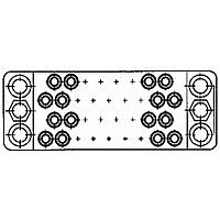
205606-3
Description
15 POS. SOC. BLOCK
Manufacturer
TE Connectivity
Type
Housingr
Datasheet
1.205606-3.pdf
(95 pages)
Specifications of 205606-3
Number Of Contacts
15POS
Number Of Contact Rows
3
Body Orientation
Straight
Pitch (mm)
5.08mm
Gender
RCP
Housing Material
Phenolic
Housing Color
Black
Product Length (mm)
41.4mm
Rohs Compliant
YES
Product Type
Housing
Type Of Connector
Posted
Mount
Panel
Mounting Hardware
None
High Voltage
No
Number Of Positions
15
Preloaded Contacts
No
Center Fastener
No
Connector Style
Receptacle
Rohs/elv Compliance
RoHS compliant, ELV compliant
Lead Free Solder Processes
Wave solder capable to 240°C, Wave solder capable to 260°C, Wave solder capable to 265°C
Rohs/elv Compliance History
Always was RoHS compliant
Lead Free Status / RoHS Status
Compliant


Dimensions are shown for reference
purposes only.
M Series
Pin and Socket Connectors
Table of Contents
Product Facts
Introduction . . . . . . . . . . . . . . . . . . . . . . . . . . . . . . . . . . . . . . 4, 5
Material Specifications . . . . . . . . . . . . . . . . . . . . . . . . . . . . . . . . . . 6
Current Carrying Capabilities . . . . . . . . . . . . . . . . . . . . . . . . . . . . . . 7, 8
How to Use this Catalog . . . . . . . . . . . . . . . . . . . . . . . . . . . . . . . . . . 9
Connector/Hardware Selection Guide (for Typical Applications)
Cable-to-Cable . . . . . . . . . . . . . . . . . . . . . . . . . . . . . . . . . . . . . . . . . . . . . . . . . . . . . . .10-17
Cable-to-Panel . . . . . . . . . . . . . . . . . . . . . . . . . . . . . . . . . . . . . . . . . . . . . . . . . . . . . . . .18-25
Contacts (Description of Types) . . . . . . . . . . . . . . . . . . . . . . . . . . . 26-29
Signal Contacts
Power Contacts
Coaxial Contacts
160 CF Positions (with Center Fastener) . . . . . . . . . . . . . . . . . . . . . . . . 51
15, 36 and 50 Positions (.200 [5.08] Grid)
Keying Hardware
Application Tooling
Technical Documents
Type II, Crimp, Snap-In
Type III+, Crimp, Snap-In; Posted; Solder Versions . . . . . . . . . . . . . . . . . 31-35
Type I, Crimp, Snap-In . . . . . . . . . . . . . . . . . . . . . . . . . . . . . . . . . 36
High Current Type II and Type III+ (Screw Machine, Crimp, Snap-In) . . . . . . . . . . 37
Type XII, Crimp, Snap-In . . . . . . . . . . . . . . . . . . . . . . . . . . . . . . . . 38
High Current Type XII (Screw Machine, Crimp, Snap-In) . . . . . . . . . . . . . . . . 39
Subminiature, Crimp, Snap-In, Size 16
Miniature, Crimp, Snap-In, Size 12 . . . . . . . . . . . . . . . . . . . . . . . . . 42, 43
Standard Housings—Introduction . . . . . . . . . . . . . . . . . . . . . . . . . . . . . 44
6, 14, and 20-Positions
26, 34 and 36-Positions
41 and 50-Positions . . . . . . . . . . . . . . . . . . . . . . . . . . . . . . . . 47, 48
75 and 104-Positions
104 CF Positions (with Center Fastener) . . . . . . . . . . . . . . . . . . . . . . . . 50
Posted Connectors—Introduction . . . . . . . . . . . . . . . . . . . . . . . . . . . . . 52
6, 14, 20 and 26-Positions . . . . . . . . . . . . . . . . . . . . . . . . . . . . . 53, 54
34 and 50 Positions
75 and 104-Positions
104 and 160 CF Positions (with Center Fastener) . . . . . . . . . . . . . . . . . . 58, 59
Special Application Connectors—Introduction . . . . . . . . . . . . . . . . . . . . . . . 61
V.35 Special Application Connectors—Introduction
V.35 Printed Circuit Board Connectors . . . . . . . . . . . . . . . . . . . . . . . 64-67
V.35 Cable Connectors . . . . . . . . . . . . . . . . . . . . . . . . . . . . . . . 68-71
12-Positions, High Current Connector (UL Voltage Rating: 1800 V) . . . . . . . . . . . 72
29 CF Position Connector with Mixed Contacts (with Center Fastener)
42-Positions, Connector with Mixed Contacts
20-Positions, High Voltage Connector (UL Voltage Rating: 1800 V) . . . . . . . . . . . 75
28-Positions, High Voltage Connector (UL Voltage Rating: 1800 V) . . . . . . . . . . . 76
14 and 34-Positions, Grounding Blocks and Fastening Hardware . . . . . . . . . . . . 77
Hardware
Fastening Hardware . . . . . . . . . . . . . . . . . . . . . . . . . . . . . . . . 78-80
Guiding Hardware . . . . . . . . . . . . . . . . . . . . . . . . . . . . . . . . . . . 81
Protective Hardware . . . . . . . . . . . . . . . . . . . . . . . . . . . . . . . . 82-87
Strain Relief Hardware . . . . . . . . . . . . . . . . . . . . . . . . . . . . . . . . . 88
Part Number Index
Dimensions are in inches and mil-
limeters unless otherwise specified.
Values in brackets are metric equiva-
lents.
. . . . . . . . . . . . . . . . . . . . . . . . . . . . . . . . . . . . . . 2
. . . . . . . . . . . . . . . . . . . . . . . . . . . . . . . . . . . 89
. . . . . . . . . . . . . . . . . . . . . . . . . . . . . . . . . 90, 91
. . . . . . . . . . . . . . . . . . . . . . . . . . . . . . . . . 94, 95
. . . . . . . . . . . . . . . . . . . . . . . . . . . . . . . . 55, 56
. . . . . . . . . . . . . . . . . . . . . . . . . . . . . . . . 92, 93
. . . . . . . . . . . . . . . . . . . . . . . . . . . . . . . . . 49
. . . . . . . . . . . . . . . . . . . . . . . . . . . . . . . . . 57
. . . . . . . . . . . . . . . . . . . . . . . . . . . . . . . . 30
. . . . . . . . . . . . . . . . . . . . . . . . . . . . . . . . 45
. . . . . . . . . . . . . . . . . . . . . . . . . . . . . . 46, 47
Specifications subject to change.
. . . . . . . . . . . . . . . . . . . . . . . . . . . . . . . . . . . .40, 41
. . . . . . . . . . . . . . . . . . . . . 59, 60
. . . . . . . . . . . . . . . . . . . . . 74
. . . . . . . . . . . . . . . . 62, 63
Technical Support Center
1-800-522-6752
www.tycoelectronics.com
. . . . . . . . . 73
Catalog 82003
Revised 3-01
3
Related parts for 205606-3
Image
Part Number
Description
Manufacturer
Datasheet
Request
R

Part Number:
Description:
Printers THERMAL PRINTER HS-SLEEVE MARKER
Manufacturer:
TE Connectivity


Part Number:
Description:
High Speed / Modular Connectors 30P HEADER ASSY
Manufacturer:
TE Connectivity
Datasheet:

Part Number:
Description:
High Speed / Modular Connectors REC 6X005P R/A LT B-PLANE HS3
Manufacturer:
TE Connectivity
Datasheet:

Part Number:
Description:
High Speed / Modular Connectors 2MM HM RCPT 50P R/A AU
Manufacturer:
TE Connectivity
Datasheet:

Part Number:
Description:
High Speed / Modular Connectors 2MM HM RCPT 50P R/A AU
Manufacturer:
TE Connectivity
Datasheet:


Part Number:
Description:
Manufacturer:
TE Connectivity
Datasheet:


Part Number:
Description:
Manufacturer:
TE Connectivity
Datasheet:

Part Number:
Description:
Manufacturer:
TE Connectivity
Datasheet:

Part Number:
Description:
Manufacturer:
TE Connectivity
Datasheet: