205606-3 TE Connectivity, 205606-3 Datasheet - Page 15
205606-3
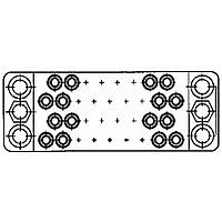
Manufacturer Part Number
205606-3
Description
15 POS. SOC. BLOCK
Manufacturer
TE Connectivity
Type
Housingr
Datasheet
1.205606-3.pdf
(95 pages)
Specifications of 205606-3
Number Of Contacts
15POS
Number Of Contact Rows
3
Body Orientation
Straight
Pitch (mm)
5.08mm
Gender
RCP
Housing Material
Phenolic
Housing Color
Black
Product Length (mm)
41.4mm
Rohs Compliant
YES
Product Type
Housing
Type Of Connector
Posted
Mount
Panel
Mounting Hardware
None
High Voltage
No
Number Of Positions
15
Preloaded Contacts
No
Center Fastener
No
Connector Style
Receptacle
Rohs/elv Compliance
RoHS compliant, ELV compliant
Lead Free Solder Processes
Wave solder capable to 240°C, Wave solder capable to 260°C, Wave solder capable to 265°C
Rohs/elv Compliance History
Always was RoHS compliant
Lead Free Status / RoHS Status
Compliant


1. Confirm that Application C (at left) most closely meets
2. Find the appropriate column for the number of positions
3. Select part numbers required for the application listed
3.
3.
4. Dimensional information is available on the indicated
5. Select Contacts: Type II (page 30), Type III+ (pages 31
Dimensions are shown for reference
purposes only.
202135-2
201302-1
202135-4
201302-3
201486-2
200389-2
200390-2
201921-1
201922-1
your requirements. (Other applications are shown on
pages 10-13 and 16 through 25.)
required.
in the column below the number of positions.
If a part number is not listed for a particular item, it is
not available.
If more than one part number is listed for a particular
hardware item, choose the one which best fits your
application.
pages under description column.
through 35) or Subminiature Coaxial (pages 40, 41).
41
—
—
—
—
—
—
—
—
—
—
—
—
—
—
—
—
—
—
—
201358-1
200277-2
201358-3
200277-4
201470-2
200389-2
200390-2
200833-2
200835-2
201925-1
201926-1
50
—
—
—
—
—
—
—
—
—
—
—
—
—
—
—
—
—
75
—
—
—
—
—
—
—
—
—
—
—
—
—
—
—
—
—
—
—
—
—
—
—
—
—
—
—
—
Number of Positions
M Series
Pin and Socket Connectors
Cable-to-Cable
Dimensions are in inches and mil-
limeters unless otherwise specified.
Values in brackets are metric equiva-
lents.
104
—
—
—
—
—
—
—
—
—
—
—
—
—
—
—
—
—
—
—
—
—
—
—
—
—
—
—
—
1-201692-6
(Continued)
104 CF
—
—
—
—
—
—
—
—
—
—
—
—
—
—
—
—
—
—
—
—
—
—
—
—
—
—
—
Special application housings may be substituted
for these standard housings. See Special Application
Section.
This cable-to-cable application utilizes locking springs,
one-piece shields, a pin hood for pin protection and guide
hardware. The shields are available with both 180° and 90°
cable exits. The 180° shields are available in a long version
which provides pin protection in lieu of a pin hood.
A short shield and a pin hood or a long shield can be used
on one side only of a mated pair of connectors. The mating
connector must use a short shield.
The 34 and 50 position connectors can be used with either
center or corner guide hardware. If center guides are used,
an additional four 4-40 screws are required to secure the
locking springs. If corner guides are used, an additional
two 4-40 screws will be required to attach the shield.
Corner guides require four guide pins and four guide
sockets for each mated pair of connectors.
160 CF
Specifications subject to change.
—
—
—
—
—
—
—
—
—
—
—
—
—
—
—
—
—
—
—
—
—
—
—
—
—
—
—
—
Plug Block
Receptacle Block
Plug Block
Receptacle Block
Plug Block
Receptacle Block
180° Two-
Piece Long
180° Two-
Piece Short
180° One-Piece Long
180° One-Piece Short
Center Male
Center Female
Corner Male
Corner Female
Male—Nickel Plated Spring Steel
Female—Stainless Steel
Internal Open End
Internal Closed End
External Closed End
External Closed End
90° Two-Piece Long
90° Two-Piece Short
45° Two-Piece Short
45° Two-Piece Deep
90° One-Piece Short
Al Anodized
Zinc Plated Steel
Al Anodized
Zinc Plated Steel
Zinc Plated Cast Al
Component Description
Phenolic
Diallyl Phthalate
Polyester
Stainless Steel
Nickel Plated Steel
Nickel Plated Steel
Al Iridite
Nickel Plated Steel
Technical Support Center
1-800-522-6752
www.tycoelectronics.com
Plated
Nickel
Steel
LOCKING SPRINGS
Catalog 82003
Pages 82 and 83
Pages 44 to 51
Pages 84 to 87
HARDWARE
STANDARD
PIN HOODS
HOUSINGS
SHIELDS
Page 81
Page 80
Revised 3-01
GUIDE
1
15
Related parts for 205606-3
Image
Part Number
Description
Manufacturer
Datasheet
Request
R

Part Number:
Description:
Printers THERMAL PRINTER HS-SLEEVE MARKER
Manufacturer:
TE Connectivity


Part Number:
Description:
High Speed / Modular Connectors 30P HEADER ASSY
Manufacturer:
TE Connectivity
Datasheet:

Part Number:
Description:
High Speed / Modular Connectors REC 6X005P R/A LT B-PLANE HS3
Manufacturer:
TE Connectivity
Datasheet:

Part Number:
Description:
High Speed / Modular Connectors 2MM HM RCPT 50P R/A AU
Manufacturer:
TE Connectivity
Datasheet:

Part Number:
Description:
High Speed / Modular Connectors 2MM HM RCPT 50P R/A AU
Manufacturer:
TE Connectivity
Datasheet:


Part Number:
Description:
Manufacturer:
TE Connectivity
Datasheet:


Part Number:
Description:
Manufacturer:
TE Connectivity
Datasheet:

Part Number:
Description:
Manufacturer:
TE Connectivity
Datasheet:

Part Number:
Description:
Manufacturer:
TE Connectivity
Datasheet: