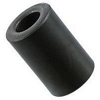
0199000019 Fair-Rite, 0199000019 Datasheet - Page 98

0199000019
Manufacturer Part Number
0199000019
Description
BEAD KIT, EMI SUPPRESSION
Manufacturer
Fair-Rite
Datasheet
1.0199000019.pdf
(715 pages)
Specifications of 0199000019
Kit Contents
Contains 28 Different Beads In Three Suppression Materials, 73, 43 And 61.
Component Type
Shield Bead Kit
Lead Free Status / RoHS Status
Lead free / RoHS Compliant
Lead Free Status / RoHS Status
Lead free / RoHS Compliant
- Current page: 98 of 715
- Download datasheet (9Mb)
Figure 1 shows the rod permeability as a function of the length to diameter ratio for the six materials available
in rods.
Figures 3, 4 and 5 illustrate typical temperature behavior of wound rods. Wound rods in 33 and 77 material yield
the best temperature stable inductors, see Figure 4. Both show a typical inductance change of < 1% over the
–40 to 120 C temperature range. The parts have a L/D ratio of 8.1. Lower ratios will change less. This is shown
in detail in Figure 5 for the same 52 material but with the L/D ratio as the parameter. A lower ratio means a lower
rod permeability but with improved temperature stability.
Wound Rod Inductance Calculations.
To calculate the inductance of a wound rod the following formula can be used.
Where: K = Inductance modifier
Rod Information
F a ir-R it e Prod uct s C o rp .
Phone:
µ rod
60
50
40
30
20
10
0
Uo = 4π10
Urod = rod permeability found in Figure 1.
N =Number of turns
Ae = Cross sectional area of the rod (cm
l = Length of the rod (cm)
lc = Length of the winding (cm)
(888) FAIR RITE / (845) 895-2055 • FAX: (888) FERRITE / (845) 895-2629
(888) 324-7748
Rod Permeabiliy vs. Rod Length divided by Rod Diameter
1
2
Rod Length/Rod Diameter
3
−7
Figure 1
4
5
6
7
8
(888) 337 -7483
9
2
)
10
Materials
K
• www.fair-rite.com
• E-Mail: ferrites@fair-rite.com
PO Box J, One Commercial Row, Wallkill, NY 12589-0288
3.0
2.5
2.0
1.5
1.0
0.5
0.0
0.0
0.2
L=kµ
Inductance Modifier K
0
µ
rod
0.4
Figure 2
N
2
l
l
A
c
/l
e
0.6
10
4
( H)
u
0.8
1.0
Related parts for 0199000019
Image
Part Number
Description
Manufacturer
Datasheet
Request
R

Part Number:
Description:
EMI/RFI Suppressors & Ferrites LF Z=95OHM @ 100MHz
Manufacturer:
Fair-Rite

Part Number:
Description:
EMI/RFI Suppressors & Ferrites Z=94ohms @ 10MHz
Manufacturer:
Fair-Rite
Datasheet:

Part Number:
Description:
EMI/RFI Suppressors & Ferrites LF Z=47OHM @ 100MHz
Manufacturer:
Fair-Rite
Datasheet:

Part Number:
Description:
EMI/RFI Suppressors & Ferrites Z=300 @ 100MHz
Manufacturer:
Fair-Rite
Datasheet:

Part Number:
Description:
EMI/RFI Suppressors & Ferrites Z=365 OHM @ 100 MHz
Manufacturer:
Fair-Rite
Datasheet:

Part Number:
Description:
EMI/RFI Suppressors & Ferrites LF Z=133OHM @ 100MHz T/R
Manufacturer:
Fair-Rite
Datasheet:

Part Number:
Description:
EMI/RFI Suppressors & Ferrites Z=132 OHM @ 100MHz
Manufacturer:
Fair-Rite
Datasheet:

Part Number:
Description:
EMI/RFI Suppressors & Ferrites Z=33 OHM @ 100MHz
Manufacturer:
Fair-Rite
Datasheet:

Part Number:
Description:
EMI/RFI Suppressors & Ferrites LF Z=78OHM @ 25MHz
Manufacturer:
Fair-Rite
Datasheet:

Part Number:
Description:
FERRITE CORE, CYLINDRICAL
Manufacturer:
Fair-Rite
Datasheet:

Part Number:
Description:
FERRITE BEAD, SMD, 350mOHM, 400mA
Manufacturer:
Fair-Rite
Datasheet:

Part Number:
Description:
FERRITE CORE, CYLINDRICAL
Manufacturer:
Fair-Rite
Datasheet:

Part Number:
Description:
FERRITE BEAD, SMD, 1.4mOHM, 5A
Manufacturer:
Fair-Rite
Datasheet:

Part Number:
Description:
CHIP BEAD,Ferrite
Manufacturer:
Fair-Rite
Datasheet:

Part Number:
Description:
SPLIT FERRITE CORE, 100MHZ, 290OHM
Manufacturer:
Fair-Rite
Datasheet:


