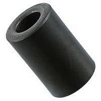
0199000019 Fair-Rite, 0199000019 Datasheet - Page 132

0199000019
Manufacturer Part Number
0199000019
Description
BEAD KIT, EMI SUPPRESSION
Manufacturer
Fair-Rite
Datasheet
1.0199000019.pdf
(715 pages)
Specifications of 0199000019
Kit Contents
Contains 28 Different Beads In Three Suppression Materials, 73, 43 And 61.
Component Type
Shield Bead Kit
Lead Free Status / RoHS Status
Lead free / RoHS Compliant
Lead Free Status / RoHS Status
Lead free / RoHS Compliant
- Current page: 132 of 715
- Download datasheet (9Mb)
132
Figure 3
Average length of turn for E 9478014002 is:
(From the Wire Table, 1000 ft of 20 AWG has a resistance of 10.2 W )
To check for winding fit, multiply the number of turns per square
inch for 20 AWG from the Wire Table with the bobbin winding area
of .069 inch
modate 854 x .069 = 58.9 turns. This is too close to the calculated
turns for an easily manufactured magnetic design. Use 21 AWG
wire instead.
Winding fit for 21 AWG:
Step 3. Air gap.
Going back to Figure 2, for LI
a
To summarize:
Fc
Technical Information
Fair-Rite Products Corp.
Phone:
l
1.0
/
.9
.8
.7
.6
.5
.4
.3
.2
.1
l
0
e
l
l
R
R
N = 1065 x .069 = 73.5, well above the require 61 turns.
The gap length = .006 x
l
E core 9478014002
Wire size 21 AWG
0.01
avg.
avg.
ratio of approximately .006 is found.
= .006 x 4.9/2.54 = .012 inch.
dc
dc
= 2.48 x 61 x 12.8/12000 = 0.16 W.
= 2 (C+F)
= 2 (.500 + .740) = 2.48 inch.
= 2.48 x 61 x 10.2/12000 = 0.13 W
(888) 324-7748
(888) FAIR RITE / (845) 895-2055 -
Correction factor F
2
. For 20 AWG, the bobbin winding area can accom-
A
w
(inch
2
0.1
/ V
l
c
e
Pot Cores
EP Cores
E Cores
PQ Cores
ETD Cores
vs. core winding area A
.
e
N = 61 turns
Gap length .012 inch
= 3.4 10
2
)
-4
and a H = 17 oersted,
FAX:
(888) FERRITE / (845) 895-2629
(888 337-7483
1.0
w
.
The graphs in Figures 4 through 8 show the inductance factors
or A
and sizes.The air gap determined in the design example and the
air gaps shown in Figures 4 through 8 represent the total air gap.
The most practical way to obtain this air gap is to grind this gap
into the center leg of one of the core halves. Non-metallic shims
can also be used to obtain the desired air gap. This is usually
done by placing shims between the outer legs or outside rims of
the core halves. In cores with a uniform cross-sectional area, the
A
is gapped or shims are used that have a thickness half the total
air gap. For cores that have a non-uniform cross-sectional area
the shim thickness can be calculated from:
The above example of the E core 9478014002, a core with a
uniform cross-sectional area, can therefore use .006 inch shims
between the outer legs.
(nH)
Figure 4 A
A
L
10000
L
value or inductance index will be the same whether the core
1000
L
100
values as a function of the air gaps for the different core types
Shim thickness = total air gap x center mating area
10
PO Box J, One Commercial Row, Wallkill, NY 12589-0288
0.001
L
-
-
vs. gap for E cores in 77 and 78 material.
www.fair-rite.com
E-Mail: ferrites@fair-rite.com
10
11
12
1
2
3
4
5
6
7
8
9
Air Gap (inch)
1-94--625002 5-94--375002 9-94--015002
2-94--500002 6-94--014002 10-94--016002
3-94--036002 7-94--012002 11-94--020002
4-94--017002 8-94--034002 12-94--019002
0.01
total mating area
15th Edition
0.1
Related parts for 0199000019
Image
Part Number
Description
Manufacturer
Datasheet
Request
R

Part Number:
Description:
EMI/RFI Suppressors & Ferrites LF Z=95OHM @ 100MHz
Manufacturer:
Fair-Rite

Part Number:
Description:
EMI/RFI Suppressors & Ferrites Z=94ohms @ 10MHz
Manufacturer:
Fair-Rite
Datasheet:

Part Number:
Description:
EMI/RFI Suppressors & Ferrites LF Z=47OHM @ 100MHz
Manufacturer:
Fair-Rite
Datasheet:

Part Number:
Description:
EMI/RFI Suppressors & Ferrites Z=300 @ 100MHz
Manufacturer:
Fair-Rite
Datasheet:

Part Number:
Description:
EMI/RFI Suppressors & Ferrites Z=365 OHM @ 100 MHz
Manufacturer:
Fair-Rite
Datasheet:

Part Number:
Description:
EMI/RFI Suppressors & Ferrites LF Z=133OHM @ 100MHz T/R
Manufacturer:
Fair-Rite
Datasheet:

Part Number:
Description:
EMI/RFI Suppressors & Ferrites Z=132 OHM @ 100MHz
Manufacturer:
Fair-Rite
Datasheet:

Part Number:
Description:
EMI/RFI Suppressors & Ferrites Z=33 OHM @ 100MHz
Manufacturer:
Fair-Rite
Datasheet:

Part Number:
Description:
EMI/RFI Suppressors & Ferrites LF Z=78OHM @ 25MHz
Manufacturer:
Fair-Rite
Datasheet:

Part Number:
Description:
FERRITE CORE, CYLINDRICAL
Manufacturer:
Fair-Rite
Datasheet:

Part Number:
Description:
FERRITE BEAD, SMD, 350mOHM, 400mA
Manufacturer:
Fair-Rite
Datasheet:

Part Number:
Description:
FERRITE CORE, CYLINDRICAL
Manufacturer:
Fair-Rite
Datasheet:

Part Number:
Description:
FERRITE BEAD, SMD, 1.4mOHM, 5A
Manufacturer:
Fair-Rite
Datasheet:

Part Number:
Description:
CHIP BEAD,Ferrite
Manufacturer:
Fair-Rite
Datasheet:

Part Number:
Description:
SPLIT FERRITE CORE, 100MHZ, 290OHM
Manufacturer:
Fair-Rite
Datasheet:


