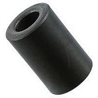
0199000019 Fair-Rite, 0199000019 Datasheet - Page 131

0199000019
Manufacturer Part Number
0199000019
Description
BEAD KIT, EMI SUPPRESSION
Manufacturer
Fair-Rite
Datasheet
1.0199000019.pdf
(715 pages)
Specifications of 0199000019
Kit Contents
Contains 28 Different Beads In Three Suppression Materials, 73, 43 And 61.
Component Type
Shield Bead Kit
Lead Free Status / RoHS Status
Lead free / RoHS Compliant
Lead Free Status / RoHS Status
Lead free / RoHS Compliant
- Current page: 131 of 715
- Download datasheet (9Mb)
15th Edition
The following example illustrates the use of the Hanna curve in
the design of an inductor.
Inductor specifications:
Step 1. Initial Core Selection.
Using the Hanna curve for 78 material of Figure 2, select a value
for LI
between 10
ferrite too hard and the dc resistance is apt to be high. Anything
lower than 10
resistance will be quite low.
Select therefore LI
Calculate V
Select E core (preferred core shape), based upon the calculated
core volume of 3.8 cm
Two Fair-Rite E cores are considered:
The 9478014002 is closest and will be used in this inductor
design. The core parameters for this E core set are:
Recalculate
Step 2. Number of Turns, Wire Size and Wire Fit.
From Figure 2, a LI
Calculate turns N from the formula H = .4
From the core dimensions, the core winding area can be
calculated, see Table 1.
Winding area for a set of E cores 9478014002 is:
Technical Information
Fair-Rite Products Corp.
Phone:
Minimum inductance
Direct current
Alternating ripple current
Maximum dc resistance
V
L
I
V
9478015002
9478014002
l
LI
N = 17 x 4.9/.4 x
A
A
2
e
min
e
e
w
w
/ V
= 4.9 cm, A
2
= .255 (.740-.250) = .125 inch
= D (E-F) in inch
/ V
e
= LI
= 1 mH, design for L = 1.1 10
= I
= 1.1 10
(888) 324-7748
(888) FAIR RITE / (845) 895-2055 -
approximately mid range on the vertical axis, that is
e
-4
e
= 1.1 10
dc
from:
and 10
2
-4
+ I
/3.5 10
will result in a conservative design and the dc
ac
-3
e
2
/2 = 1 + 0.2/2 = 1.1 A
2
= .80 cm
x 1.1
/ V
/ V
-3
-3
V
V
. Any value greater than 10
-4
p
3
x 1.1
e
e
e
e
from the catalog, pages 118 and 120.
= 1.95 cm
= 3.92 cm
= 3.4 10
= 3.5 10
x 1.1 = 60.3 or 61 turns.
2
2
.
/3.5 10
2
/3.92 = 3.4 10
2
and V
-4
-4
-4
yields a H value of 17 oersted.
3
L
I
I
R
3
dc
ac
= 3.8 cm
.
and
dc
e
= 3.92 cm
= 1 mH
= 1 A
= 0.2 A
< 0.2
2
.
-3
H
-4
p
.
3
W
NI /
FAX:
3
.
l
-3
e
(888) FERRITE / (845) 895-2629
(888 337-7483
will work the
oersted.
Figure 2
Since the winding area of the appropriate bobbin is smaller than
the core winding area, a correction factor F
determine the bobbin winding area. Figure 3 gives this correction
factor F
A set of E cores 9478014002 has a A
3 can be determined that the F
winding area is .55 x .125 = .069 inch
current density of 1 mA per circular mil or 1275 A per inch
initial wire size selection of 20 AWG can be made from the Wire
Table on page 137. To determine the dc resistance of the winding,
first find the average length of turn from Table 2.
LI
V
e
2
10
10
10
10
-2
-3
-4
-5
c
1
as a function of the calculated core winding area A
Hanna curve for core sets in 78 material.
e
= air gap
= effective path length of core set
PO Box J, One Commercial Row, Wallkill, NY 12589-0288
-
-
Table 2
Mean Length of Turn (inch)
Table 1
Core Winding Area (inch
www.fair-rite.com
E-Mail: ferrites@fair-rite.com
E Cores
ETD Cores
PQ Cores
Pot Cores
EP Cores
E Cores
ETD Cores
PQ Cores
Pot Cores
EP Cores
e
10
=.002
H (oersted)
=.005
=.010
c
= .55, therefore the bobbin
=.015
w
.5 p (E+F)
.5 p (E+F)
.5 p (E+F)
.5 p (E+F)
= .125 inch
2 (C+E)
D(E-F)
D(E-F)
D(E-F)
D(E-F)
D(E-F)
=.020
2
2
100
. Using a conservative
)
=.050
=.070
c
has to be used to
=.100
=.150
2
, from Figure
1000
2
, an
131
w
.
Related parts for 0199000019
Image
Part Number
Description
Manufacturer
Datasheet
Request
R

Part Number:
Description:
EMI/RFI Suppressors & Ferrites LF Z=95OHM @ 100MHz
Manufacturer:
Fair-Rite

Part Number:
Description:
EMI/RFI Suppressors & Ferrites Z=94ohms @ 10MHz
Manufacturer:
Fair-Rite
Datasheet:

Part Number:
Description:
EMI/RFI Suppressors & Ferrites LF Z=47OHM @ 100MHz
Manufacturer:
Fair-Rite
Datasheet:

Part Number:
Description:
EMI/RFI Suppressors & Ferrites Z=300 @ 100MHz
Manufacturer:
Fair-Rite
Datasheet:

Part Number:
Description:
EMI/RFI Suppressors & Ferrites Z=365 OHM @ 100 MHz
Manufacturer:
Fair-Rite
Datasheet:

Part Number:
Description:
EMI/RFI Suppressors & Ferrites LF Z=133OHM @ 100MHz T/R
Manufacturer:
Fair-Rite
Datasheet:

Part Number:
Description:
EMI/RFI Suppressors & Ferrites Z=132 OHM @ 100MHz
Manufacturer:
Fair-Rite
Datasheet:

Part Number:
Description:
EMI/RFI Suppressors & Ferrites Z=33 OHM @ 100MHz
Manufacturer:
Fair-Rite
Datasheet:

Part Number:
Description:
EMI/RFI Suppressors & Ferrites LF Z=78OHM @ 25MHz
Manufacturer:
Fair-Rite
Datasheet:

Part Number:
Description:
FERRITE CORE, CYLINDRICAL
Manufacturer:
Fair-Rite
Datasheet:

Part Number:
Description:
FERRITE BEAD, SMD, 350mOHM, 400mA
Manufacturer:
Fair-Rite
Datasheet:

Part Number:
Description:
FERRITE CORE, CYLINDRICAL
Manufacturer:
Fair-Rite
Datasheet:

Part Number:
Description:
FERRITE BEAD, SMD, 1.4mOHM, 5A
Manufacturer:
Fair-Rite
Datasheet:

Part Number:
Description:
CHIP BEAD,Ferrite
Manufacturer:
Fair-Rite
Datasheet:

Part Number:
Description:
SPLIT FERRITE CORE, 100MHZ, 290OHM
Manufacturer:
Fair-Rite
Datasheet:


