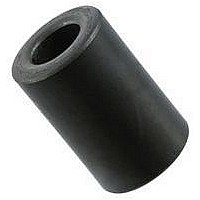
0199000019 Fair-Rite, 0199000019 Datasheet - Page 135

0199000019
Manufacturer Part Number
0199000019
Description
BEAD KIT, EMI SUPPRESSION
Manufacturer
Fair-Rite
Datasheet
1.0199000019.pdf
(715 pages)
Specifications of 0199000019
Kit Contents
Contains 28 Different Beads In Three Suppression Materials, 73, 43 And 61.
Component Type
Shield Bead Kit
Lead Free Status / RoHS Status
Lead free / RoHS Compliant
Lead Free Status / RoHS Status
Lead free / RoHS Compliant
- Current page: 135 of 715
- Download datasheet (9Mb)
Technical Information
15th Edition
F air-Rite Produ cts Cor p.
Phone:
Use of Ferrites in Broadband Transformers
Introduction
Most of the magnetic information in this catalog is data obtained
from cores wound with a single multi-turn-winding which forms
an inductor. When a second winding is added on the core, the
inductor becomes a transformer. Depending on the require-
ments, transformers can be designed to provide dc isolation,
impedance matching and specific current or voltage ratios.
Transformer designed for power, broadband, pulse, or imped-
ance matching can often be used over a broad frequency
spectrum.
In many transformer designs ferrites are used as the core
material. This article will address the properties of the ferrite
materials and core geometries which are of concern in the
design of low power broadband transformers.
Brief Theory
Broadband transformers are wound magnetic devices that are
designed to transfer energy over a wide frequency range. Most
applications for broadband transformers are in telecommunica-
tion equipment where they are extensively used at a low power
levels.
Figure 1 shows a typical performance curve of insertion loss
as a function of frequency for a broadband transformer. The
bandwidth of a broadband transformer is the frequency differ-
ence between f
of the specified insertion loss and the transformer roll-off
characteristics.
It can be seen that the bandwidth is narrower for transformers
with a steep roll-off (f
off (f
identified.
The cutoff frequencies are determined by the requirements of the
individual broadband transformer design. Therefore, f
greater than 10 MHz or less than 300 Hz. Bandwidths also can
vary from a few hundred hertz to hundreds of MHz. A typical
2
- f
1
(888) FAIR RITE / (845) 895-2055 • FAX: (888) FERRITE / (845) 895-2629
(888) 324-7748
). Also in Figure 1, the three frequency regions are
2
and f
2
'- f
1
, or between f
1
' ) than those with a more gradual roll-
2
' and f
1
', and is a function
(888) 337 -7483
1
can be
broadband transformer design will specify for the mid frequency
range a maximum insertion loss and for the cutoff frequencies,
f
diagram of the lumped element equivalent circuit of a trans-
former, separating the circuit into an ideal transformer, its com-
ponents and equivalent parasitic resistances and reactances.
The secondary components, parasitics and the load resistance
have been transferred to the primary side and are identified with
a prime.
To simplify this circuit, the primary and secondary circuit ele-
ments have been combined and the equivalent reduced circuit
is a shown in Figure 3. The physical significance of the param-
eters are listed below the equivalent circuits. In the low frequency
region the roll-off in transmission characteristics is due a lower-
ing of the shunt impedance. The shunt impedance decreases
when the frequency is reduced, which results in the increases
level of attenuation. The impedance is mainly a function of the
Figure 1 Typical Characteristic Curve of Insertion Loss vs.
1
and f
Low Frequency
Region
2
• www.fair-rite.com
• E-Mail: ferrites@fair-rite.com
maximum allowable losses. Figure 2 is a schematic
PO Box J, One Commercial Row, Wallkill, NY 12589-0288
Frequency for a broadband transformer.
f
1
f
1
'
Frequency
Mid-Band
Region
High Frequency
Region
f
2
'
f
2
135
Related parts for 0199000019
Image
Part Number
Description
Manufacturer
Datasheet
Request
R

Part Number:
Description:
EMI/RFI Suppressors & Ferrites LF Z=95OHM @ 100MHz
Manufacturer:
Fair-Rite

Part Number:
Description:
EMI/RFI Suppressors & Ferrites Z=94ohms @ 10MHz
Manufacturer:
Fair-Rite
Datasheet:

Part Number:
Description:
EMI/RFI Suppressors & Ferrites LF Z=47OHM @ 100MHz
Manufacturer:
Fair-Rite
Datasheet:

Part Number:
Description:
EMI/RFI Suppressors & Ferrites Z=300 @ 100MHz
Manufacturer:
Fair-Rite
Datasheet:

Part Number:
Description:
EMI/RFI Suppressors & Ferrites Z=365 OHM @ 100 MHz
Manufacturer:
Fair-Rite
Datasheet:

Part Number:
Description:
EMI/RFI Suppressors & Ferrites LF Z=133OHM @ 100MHz T/R
Manufacturer:
Fair-Rite
Datasheet:

Part Number:
Description:
EMI/RFI Suppressors & Ferrites Z=132 OHM @ 100MHz
Manufacturer:
Fair-Rite
Datasheet:

Part Number:
Description:
EMI/RFI Suppressors & Ferrites Z=33 OHM @ 100MHz
Manufacturer:
Fair-Rite
Datasheet:

Part Number:
Description:
EMI/RFI Suppressors & Ferrites LF Z=78OHM @ 25MHz
Manufacturer:
Fair-Rite
Datasheet:

Part Number:
Description:
FERRITE CORE, CYLINDRICAL
Manufacturer:
Fair-Rite
Datasheet:

Part Number:
Description:
FERRITE BEAD, SMD, 350mOHM, 400mA
Manufacturer:
Fair-Rite
Datasheet:

Part Number:
Description:
FERRITE CORE, CYLINDRICAL
Manufacturer:
Fair-Rite
Datasheet:

Part Number:
Description:
FERRITE BEAD, SMD, 1.4mOHM, 5A
Manufacturer:
Fair-Rite
Datasheet:

Part Number:
Description:
CHIP BEAD,Ferrite
Manufacturer:
Fair-Rite
Datasheet:

Part Number:
Description:
SPLIT FERRITE CORE, 100MHZ, 290OHM
Manufacturer:
Fair-Rite
Datasheet:


