HFBR-0527P Avago Technologies US Inc., HFBR-0527P Datasheet - Page 8
HFBR-0527P
Manufacturer Part Number
HFBR-0527P
Description
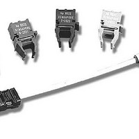
Fiber Optics, Evaluation Kit
Manufacturer
Avago Technologies US Inc.
Specifications of HFBR-0527P
Kit Contents
TX/RX Mods, Cable, Pol Kit, SW, Pwr. Sup
Tool / Board Applications
Fiber Optic Transceivers
Mcu Supported Families
HFBR-1527, HFBR-2526
Main Purpose
Interface, Fiber Optics
Embedded
No
Utilized Ic / Part
HFBR-1527, HFBR-2526
Primary Attributes
125MBd, Communication up to 25m
Secondary Attributes
650nm LED, 1mm POF
Description/function
Fiber Optic Kit
Lead Free Status / RoHS Status
Lead free / RoHS Compliant
For Use With/related Products
HFBR-1527, HFBR-2526
Lead Free Status / RoHS Status
Lead free / RoHS Compliant, Lead free / RoHS Compliant
Other names
516-2143
HFBR-0527P
HFBR-0527P


Figure 7. +5 V ECL Receiver with Through Hole Pin Out
The 125 MBd receiver shown in Figure 7 typically provides a
sensitivity of -28 dBm average modulated when used with
1 mm plastic fibers. The same receiver can be used with
200 µm HCS
of -29 dBm average modulated at a data rate of 125 MBd.
Overload characteristics of the receiver are not influenced
by characteristics of the MC10H116 quantizer. The maxi-
mum power which can be applied to the receiver shown in
Figure 7 is determined by the saturation characteristics of
the transimpedance amplifier used in the HFBR-25X6Z. The
HFBR-25X6Z is guaranteed to provide pulse width distor-
tion which is less than 2 ns when received optical power
is less than -9.4 dBm peak. Many features have been incor-
porated into the receiver recommended in this publication,
but one of the most prominent characteristics of the circuit
shown in Figure 7 is that all of the active and passive com-
ponents needed to build 10,000 fiber optic receivers can be
purchased for about $12.00 per circuit.
Notes:
VBB: Bias supply for device as a Schmitt trigger or served as stable reference voltage
Pin 11: VBB output pin
8
POWER
5
IN
8
+5V
0V
0.47 µF
HFBR-25X6Z
10 µF
C9
TM
C23
4.7 Ω
R13
U3
fibers and will provide a typical sensitivity
+
4
3
2
1
4.7 Ω
0.1 µF
R12
C10
0.1 µF
C22
2.7 µH
2.7 µH
L2
0.1 µF
0.1 µF
L1
C11
C12
V BB
V cc
+
1K Ω
R15
1K Ω
R14
10 µF
C20
10
9
V BB
1
V cc
1/3
V cc
11
0.1 µF
0.1 µF
10 µF
C19
16
C13
C14
10H116
6
U4B
7
51 Ω
+
R16
+3V
+3V
51 Ω
R17
A Complete Fiber Optic Transceiver Solution
Figure 8 shows the schematic for a complete fiber optic
transceiver. This transceiver is constructed on a printed
circuit, which is 1" wide by 1.6" long, using surface mount
components. When the transceiver shown in Figure 8 is
tested at a data rate of 125 MBd, using 100 m of 200 µm
HCS
BER of 1x10
shown in Figure 9 are recommended for use with the trans-
ceiver shown in Figure 8. The artwork for the surface mount
transceiver is shown in Figure 10, and a complete parts list
is shown in Table 1. Designers interested in inexpensive
solutions are encouraged to embed the complete fiber
optic transceiver described in this Application Note into the
next generation of new data communication products.
62 Ω
12 Ω
R21
0.1 µF
R20
C17
10H116
U4A
TM
5
4
fiber, it provides a typical eye opening of 5.4 ns at a
1/3
8
2
3
-9
TL431-CLP
. The power supply filter and ECL terminations
51 Ω
51 Ω
R18
R19
U5
0.1 µF
0.1 µF
C16
C15
0.1 µF
C18
1K Ω
1K Ω
R22
R23
V BB
V BB
13
12
1K Ω
R25
1K Ω
R24
10H116
U4C
1/3
15
14
51 Ω
51 Ω
R27
R26
ECL
ECL
Related parts for HFBR-0527P
Image
Part Number
Description
Manufacturer
Datasheet
Request
R

Part Number:
Description:
Fiber Optic Transmitters, Receivers, Transceivers 1300nm 155MBd 16-pin DIP ST Rx
Manufacturer:
Avago Technologies US Inc.

Part Number:
Description:
FIBER OPTIC TX 125 MBD 650N
Manufacturer:
Avago Technologies US Inc.
Datasheet:

Part Number:
Description:
Fiber Optic Evaluation Kit
Manufacturer:
Avago Technologies US Inc.
Datasheet:

Part Number:
Description:
RECEIVER FIBER OPTIC ST 266MBD
Manufacturer:
Avago Technologies US Inc.
Datasheet:

Part Number:
Description:
RCVR OPT HI SPEED VERS LINK HORZ
Manufacturer:
Avago Technologies US Inc.
Datasheet:

Part Number:
Description:
RCVR OPT HI SPEED VERS LINK VERT
Manufacturer:
Avago Technologies US Inc.
Datasheet:

Part Number:
Description:
TXRX OPTICAL 850NM VCSEL MT-RJ
Manufacturer:
Avago Technologies US Inc.
Datasheet:

Part Number:
Description:
TXRX MM SFP LC CONN BAIL DELATCH
Manufacturer:
Avago Technologies US Inc.
Datasheet:

Part Number:
Description:
TXRX MMF SFP GBE/FC BAIL DELATCH
Manufacturer:
Avago Technologies US Inc.
Datasheet:

Part Number:
Description:
XMITTER FIBER OPTIC 266MBD ST
Manufacturer:
Avago Technologies US Inc.
Datasheet:

Part Number:
Description:
OPTOCOUPLER GATE DRV 2A 16-SOIC
Manufacturer:
Avago Technologies US Inc.
Datasheet:
Part Number:
Description:
OPTOCOUPLER 2CH 2.5A 16-SOIC
Manufacturer:
Avago Technologies US Inc.
Datasheet:

Part Number:
Description:
OPTOCOUPLER GATE DRV 0.4A 16SOIC
Manufacturer:
Avago Technologies US Inc.
Datasheet:

Part Number:
Description:
OPTOCOUPLER 2.0A 250KHZ 8-DIP
Manufacturer:
Avago Technologies US Inc.
Datasheet:

Part Number:
Description:
OPTOCOUPLER 2.0A 250KHZ GW 8-SMD
Manufacturer:
Avago Technologies US Inc.
Datasheet: