HFBR-0527P Avago Technologies US Inc., HFBR-0527P Datasheet - Page 2
HFBR-0527P
Manufacturer Part Number
HFBR-0527P
Description
Fiber Optics, Evaluation Kit
Manufacturer
Avago Technologies US Inc.
Specifications of HFBR-0527P
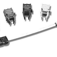
Kit Contents
TX/RX Mods, Cable, Pol Kit, SW, Pwr. Sup
Tool / Board Applications
Fiber Optic Transceivers
Mcu Supported Families
HFBR-1527, HFBR-2526
Main Purpose
Interface, Fiber Optics
Embedded
No
Utilized Ic / Part
HFBR-1527, HFBR-2526
Primary Attributes
125MBd, Communication up to 25m
Secondary Attributes
650nm LED, 1mm POF
Description/function
Fiber Optic Kit
Lead Free Status / RoHS Status
Lead free / RoHS Compliant
For Use With/related Products
HFBR-1527, HFBR-2526
Lead Free Status / RoHS Status
Lead free / RoHS Compliant, Lead free / RoHS Compliant
Other names
516-2143
HFBR-0527P
HFBR-0527P


100
180
140
HFBR-15X7Z/25X6Z Distance and Data Rate Capabilities
Various distances and data rates are possible when the
HFBR-15X7Z and HFBR-25X6Z components are used with
large-core step index fibers. At low data rates, the distances
achievable are determined by the sensitivity of the receiver,
cable attenuation, and the amount of light which the LED
can launch into the fiber core. As data rate increases, fiber
bandwidth will begin to influence how long the optical
data link can be and how fast the data can be transmitted.
A plastic fiber with a 1 mm core diameter will couple more
light from the LED than a composite fiber with a 200 µm
diameter silica glass core and plastic cladding, but greater
distances are achievable with the composite fiber since it
has significantly lower attenuation than an all-plastic fiber.
The distance data rate curves shown in Figures 1 and 2 are
provided to allow designers to quickly determine if HFBR-
15X7Z and HFBR-25X6Z can be used with large-core optical
fibers to meet their system requirements. Figure 1 shows
the distances and data rates that can be achieved with
Avago’s 1 mm plastic fibers and Figure 2 shows what can
be accomplished when using Avago’s 200 µm hard clad
silica fibers. If designers utilize the circuits recommended
in this application note, digital fiber optic links can nor-
mally be implemented at distances and data rates within
the shaded portions of Figure 1 and Figure 2. The fiber
optic transceiver shown in this publication was optimized
for operation at 125 MBd. Greater distances can be achieved
at data rates less than 125 MBd by optimizing the trans-
mitter and receiver circuits for operation at lower speeds.
80
60
40
20
10
Figure 1. Distances and Data Rates Possible with 1 mm Plastic Fiber
2
1.0
OPERATING REGION
RECOMMENDED
140
100
180
80
40
20
10
60
1.0
25
l, LENGTH, METERS
TYPICAL PERFORMANCE AT 25 C
RECOMMENDED OPERATING REGION
l
, LENGTH, METERS
25
50
TYPICAL PERFORMANCE
AT 25 C
5439-2
75
50
100
180
140
100
75
80
40
20
10
60
180
140
100
80
60
40
20
10
Figure 1 shows the performance possible with 1 mm diam-
eter plastic fiber. The HFBR-15X7Z/25X6Z components can
be used with standard 1 mm plastic cables to build 20 m
links which are capable of transmitting data at a rate of 125
MBd. When low loss plastic fiber is used, distances of 25 m
are possible at 125 MBd. As data rate decreases, the dis-
tance achievable with 1 mm fiber increases. Figure 1 shows
that a distance of 100 m is typically possible at rates as low
as 33 MBd when using low loss 1 mm plastic fiber.
Composite fiber with a silica glass core and plastic cladding
can achieve greater distances than possible with an all
plastic fiber. Figure 2 shows what can be accomplished
when HFBR-15X7Z and HFBR-25X6Z components are
used with 200 µm diameter hard clad silica (HCS) fiber.
Substantial increases in cable length are possible when
using 200 µm HCS
cal attenuation than 1 mm plastic fiber. Figure 2 indicates
that 125 MBd data rates are typically possible with 125 m
lengths of 200 µm HCS
recommended in this publication. Distances of 1 km can
typically be achieved at data rates as low as 20 MBd due to
the much lower optical losses of 200 µm HCS
HCS is a registered trademark of OFS.
Figure 2. Distances and Data Rates Possible with 200 µm HCS Fiber
1.0
1.0
100
OPERATING REGION
RECOMMENDED
TYPICAL PERFORMANCE AT 25 C
RECOMMENDED OPERATING REGION
l
, LENGTH, METERS
TM
fiber since it has a much lower opti-
l, LENGTH, METERS
TM
fiber when using the transceiver
100
100
TYPICAL PERFORMANCE
AT 25 C
TM
cable.
1,000
1,000
Related parts for HFBR-0527P
Image
Part Number
Description
Manufacturer
Datasheet
Request
R

Part Number:
Description:
Fiber Optic Transmitters, Receivers, Transceivers 1300nm 155MBd 16-pin DIP ST Rx
Manufacturer:
Avago Technologies US Inc.

Part Number:
Description:
FIBER OPTIC TX 125 MBD 650N
Manufacturer:
Avago Technologies US Inc.
Datasheet:

Part Number:
Description:
Fiber Optic Evaluation Kit
Manufacturer:
Avago Technologies US Inc.
Datasheet:

Part Number:
Description:
RECEIVER FIBER OPTIC ST 266MBD
Manufacturer:
Avago Technologies US Inc.
Datasheet:

Part Number:
Description:
RCVR OPT HI SPEED VERS LINK HORZ
Manufacturer:
Avago Technologies US Inc.
Datasheet:

Part Number:
Description:
RCVR OPT HI SPEED VERS LINK VERT
Manufacturer:
Avago Technologies US Inc.
Datasheet:

Part Number:
Description:
TXRX OPTICAL 850NM VCSEL MT-RJ
Manufacturer:
Avago Technologies US Inc.
Datasheet:

Part Number:
Description:
TXRX MM SFP LC CONN BAIL DELATCH
Manufacturer:
Avago Technologies US Inc.
Datasheet:

Part Number:
Description:
TXRX MMF SFP GBE/FC BAIL DELATCH
Manufacturer:
Avago Technologies US Inc.
Datasheet:

Part Number:
Description:
XMITTER FIBER OPTIC 266MBD ST
Manufacturer:
Avago Technologies US Inc.
Datasheet:

Part Number:
Description:
OPTOCOUPLER GATE DRV 2A 16-SOIC
Manufacturer:
Avago Technologies US Inc.
Datasheet:
Part Number:
Description:
OPTOCOUPLER 2CH 2.5A 16-SOIC
Manufacturer:
Avago Technologies US Inc.
Datasheet:

Part Number:
Description:
OPTOCOUPLER GATE DRV 0.4A 16SOIC
Manufacturer:
Avago Technologies US Inc.
Datasheet:

Part Number:
Description:
OPTOCOUPLER 2.0A 250KHZ 8-DIP
Manufacturer:
Avago Technologies US Inc.
Datasheet:

Part Number:
Description:
OPTOCOUPLER 2.0A 250KHZ GW 8-SMD
Manufacturer:
Avago Technologies US Inc.
Datasheet: