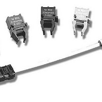
HFBR-0527P Avago Technologies US Inc., HFBR-0527P Datasheet - Page 3

HFBR-0527P
Manufacturer Part Number
HFBR-0527P
Description
Fiber Optics, Evaluation Kit
Manufacturer
Avago Technologies US Inc.
Specifications of HFBR-0527P
Kit Contents
TX/RX Mods, Cable, Pol Kit, SW, Pwr. Sup
Tool / Board Applications
Fiber Optic Transceivers
Mcu Supported Families
HFBR-1527, HFBR-2526
Main Purpose
Interface, Fiber Optics
Embedded
No
Utilized Ic / Part
HFBR-1527, HFBR-2526
Primary Attributes
125MBd, Communication up to 25m
Secondary Attributes
650nm LED, 1mm POF
Description/function
Fiber Optic Kit
Lead Free Status / RoHS Status
Lead free / RoHS Compliant
For Use With/related Products
HFBR-1527, HFBR-2526
Lead Free Status / RoHS Status
Lead free / RoHS Compliant, Lead free / RoHS Compliant
Other names
516-2143
HFBR-0527P
HFBR-0527P
Advantages of Encoded Run Limited Data
Fiber optic transceivers are commonly used in systems
that use some form of encoding. When data is encoded the
original data bits are replaced with a different group of bits
known as a symbol.
Data is encoded to prevent the digital information from
remaining in one of the two possible logic states for an
indefinite period of time. When data is encoded, a char-
acteristic known as the “run limit” is established. If data is
not changing, the run limit defines how much time may
pass before the encoder inserts a transition from one logic
state to another. The run length, or run limit of the encoder,
is the number of symbol periods that are allowed to pass
before the encoder changes logic state. Encoders also
force the encoded data to have a 50% duty factor, or they
restrict the duty factor to a limited range, such as 40 to
60%. When data is encoded, the fiber optic receiver can
be AC coupled as shown in Figure 3. Without encoding,
the fiber optic receiver would need to detect DC levels to
determine the proper logic state during long periods of
inactivity, as when there is no change in the transmitted
data. AC-coupled fiber optic receivers tend to be lower in
cost, are much easier to design, and contain fewer compo-
nents than their DC-coupled counterparts.
The output of the HFBR-25X6Z should not be direct cou-
pled to the amplifier and comparator shown in Figure 3.
Direct coupling decreases the sensitivity of a digital fiber
optic receiver, since it allows low-frequency flicker noise
from transistor amplifiers to be presented to the receiver’s
comparator input. Any undesired signals coupled to the
comparator will reduce the signal-to-noise ratio at this
critical point in the circuit, and reduce the sensitivity of the
fiber optic receiver.
Figure 3. Fiber Optic Receiver Block Diagram
3
SYSTEM
POWER
NOISY
HFBR-25X6Z
0V
+5V
RECEIVER
COMMON
SUPPLY
POWER
FILTER
AMPLIFIER
LIMITING
RECEIVER V cc
COMPARATOR
LOGIC
Another problem associated with direct-coupled receivers
is the accumulation of DC offset. With direct coupling, the
receiver’s gain stages amplify the effects of undesirable off-
sets and voltage drifts due to temperature changes. These
amplified DC offsets will eventually be applied to the com-
parator and result in reduced sensitivity of the fiber optic
receiver. The DC offset at the comparator can be referred to
the optical input of the receiver by dividing by the receiver
gain. This division refers the DC offset at the comparator
to the receiver input where it appears as a change in
optical power that must be exceeded before the receiver
will switch logic states. Problems with DC drift can be
avoided by constructing the receiver as shown in Figure 3.
Encoding has other advantages. Encoding merges the data
and clock signals in a manner that allows a timing-recovery
circuit to reconstruct the clock at the receiver end of the
digital data link. This is essential because fiber optic links
can send data at such high rates that asynchronous timing-
recovery techniques, such as over-sampling, are not very
practical. Without encoding, the clock signal required to
synchronously detect the data would need to be sent via
a second fiber optic link. Separate transmission channels
for data and clock signals are usually avoided due to cost,
but problems with time skew between the data and clock
can also arise if separate fibers are used to transmit these
signals.
COMPATIBLE
OUTPUTS
LOGIC


