HFBR-0527P Avago Technologies US Inc., HFBR-0527P Datasheet - Page 10
HFBR-0527P
Manufacturer Part Number
HFBR-0527P
Description
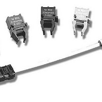
Fiber Optics, Evaluation Kit
Manufacturer
Avago Technologies US Inc.
Specifications of HFBR-0527P
Kit Contents
TX/RX Mods, Cable, Pol Kit, SW, Pwr. Sup
Tool / Board Applications
Fiber Optic Transceivers
Mcu Supported Families
HFBR-1527, HFBR-2526
Main Purpose
Interface, Fiber Optics
Embedded
No
Utilized Ic / Part
HFBR-1527, HFBR-2526
Primary Attributes
125MBd, Communication up to 25m
Secondary Attributes
650nm LED, 1mm POF
Description/function
Fiber Optic Kit
Lead Free Status / RoHS Status
Lead free / RoHS Compliant
For Use With/related Products
HFBR-1527, HFBR-2526
Lead Free Status / RoHS Status
Lead free / RoHS Compliant, Lead free / RoHS Compliant
Other names
516-2143
HFBR-0527P
HFBR-0527P


Figure 9. Recommended Power Supply Filter and +5 V ECL Signal Terminations
Figure 10a. Drill Drawing
Figure 10e. Second Layer
WARNING: DO NOT USE PHOTOCOPIES OR FAX COPIES OF THIS ARTWORK TO FABRICATE PRINTED CIRCUITS.
10
+
+
+
+
+
++ +
5439-9
+
+
+
+
+
+
+ + + + + + +
+
+
+
+
+ +
+
+
+ +
+
++
SERIAL DATA
SERIAL DATA
+ +
+
+
RECEIVER
SOURCE
+5V ECL
+5V ECL
+ +
+
+
+
+
+
+
+
+
+
+
+
+ +
+
+
+
+
+
+
+
+
0.1
Figure 10f. Third Layer
µF
82 Ω
5V
–
120
+
Ω
U2
Figure 10b. Top Silkscreen
J1
R24
C13
C7
C6
C5
TX
120
+
Ω
C15
R14
C16
U4
82 Ω
C12
C19
R19
RX
R17
C11
R16
R18 C14
+
R20 C18
R15
C17
U5
U3
+
Figure 10g. Bottom Layer
+
10
µF
10
µF
0.1
µF
0.1
µF
Figure 10c. Top Side Solder Mask
4.7 µH
0.1
µF
82 Ω
82 Ω
120 Ω
4.7 µH
4.7 µH
Figure 10h. Bottom Side Solder
Mask
120 Ω
9 T x V EE
8 TD
7 TD
6 T x V cc
5 R x V cc
4
3 RD
2 RD
1 R x V EE
Figure 10d. Top Layer
TRANSCEIVER
Figure 10i. Bottom Silkscreen
FIBER-OPTIC
SHOWN IN
0
FIGURE 8
2
C
+
6
3
R
Q
1
Q
0
1
2
C
Q
2
3
1
1
R
R
Related parts for HFBR-0527P
Image
Part Number
Description
Manufacturer
Datasheet
Request
R

Part Number:
Description:
Fiber Optic Transmitters, Receivers, Transceivers 1300nm 155MBd 16-pin DIP ST Rx
Manufacturer:
Avago Technologies US Inc.

Part Number:
Description:
FIBER OPTIC TX 125 MBD 650N
Manufacturer:
Avago Technologies US Inc.
Datasheet:

Part Number:
Description:
Fiber Optic Evaluation Kit
Manufacturer:
Avago Technologies US Inc.
Datasheet:

Part Number:
Description:
RECEIVER FIBER OPTIC ST 266MBD
Manufacturer:
Avago Technologies US Inc.
Datasheet:

Part Number:
Description:
RCVR OPT HI SPEED VERS LINK HORZ
Manufacturer:
Avago Technologies US Inc.
Datasheet:

Part Number:
Description:
RCVR OPT HI SPEED VERS LINK VERT
Manufacturer:
Avago Technologies US Inc.
Datasheet:

Part Number:
Description:
TXRX OPTICAL 850NM VCSEL MT-RJ
Manufacturer:
Avago Technologies US Inc.
Datasheet:

Part Number:
Description:
TXRX MM SFP LC CONN BAIL DELATCH
Manufacturer:
Avago Technologies US Inc.
Datasheet:

Part Number:
Description:
TXRX MMF SFP GBE/FC BAIL DELATCH
Manufacturer:
Avago Technologies US Inc.
Datasheet:

Part Number:
Description:
XMITTER FIBER OPTIC 266MBD ST
Manufacturer:
Avago Technologies US Inc.
Datasheet:

Part Number:
Description:
OPTOCOUPLER GATE DRV 2A 16-SOIC
Manufacturer:
Avago Technologies US Inc.
Datasheet:
Part Number:
Description:
OPTOCOUPLER 2CH 2.5A 16-SOIC
Manufacturer:
Avago Technologies US Inc.
Datasheet:

Part Number:
Description:
OPTOCOUPLER GATE DRV 0.4A 16SOIC
Manufacturer:
Avago Technologies US Inc.
Datasheet:

Part Number:
Description:
OPTOCOUPLER 2.0A 250KHZ 8-DIP
Manufacturer:
Avago Technologies US Inc.
Datasheet:

Part Number:
Description:
OPTOCOUPLER 2.0A 250KHZ GW 8-SMD
Manufacturer:
Avago Technologies US Inc.
Datasheet: