HFBR-0527P Avago Technologies US Inc., HFBR-0527P Datasheet
HFBR-0527P
Specifications of HFBR-0527P
HFBR-0527P


Related parts for HFBR-0527P


HFBR-0527P Summary of contents
Page 1
... The HFBR-15X7Z LED transmitter and the HFBR-25X6Z receiver can be used with large diameter 1 mm plastic or 200 µm Hard Clad Silica (HCS fibers to build unusually low cost data communication equipment ...
Page 2
... The distance data rate curves shown in Figures 1 and 2 are 60 provided to allow designers to quickly determine if HFBR- 40 15X7Z and HFBR-25X6Z can be used with large-core optical fibers to meet their system requirements. Figure 1 shows the distances and data rates that can be achieved with 20 Avago’ plastic fibers and Figure 2 shows what can be accomplished when using Avago’ ...
Page 3
... AC-coupled fiber optic receivers tend to be lower in cost, are much easier to design, and contain fewer compo- nents than their DC-coupled counterparts. The output of the HFBR-25X6Z should not be direct cou- pled to the amplifier and comparator shown in Figure 3. Direct coupling decreases the sensitivity of a digital fiber optic receiver, since it allows low-frequency flicker noise from transistor amplifiers to be presented to the receiver’ ...
Page 4
Characteristics of Encoders A Manchester encoder replaces each bit with two symbols, for instance, a logic “1” is replaced by a (“1”,“0”) symbol, and a logic “0” is replaced by a (“0”, “1”) symbol. Manchester code is not very efficient ...
Page 5
... Recommended Transmitter The transmitter shown in Figure 5 is recommended for use with 1 mm plastic fiber. The transmitter in Figure 5 applies a forward current the HFBR-15X7Z LED. If 200 µm HCS TM fiber used the LED forward current must be increased and the drive circuit shown in Figure 6 is recommended ...
Page 6
... U1B 4 7 Fiber 0.001 0.001 C5 C6 µF µF 10 0.1 µF µ HFBR-15X7Z 2 R8 300 Ω R9 300 Ω Q3 2N3904 R10 15 Ω R11 1K Ω 0.001 0.001 C5 C6 µF µF 10 0.1 µF µ HFBR-15X7Z 2 R8 82Ω Ω Q3 2N3904 R10 15 Ω C8 120 pF R11 470 Ω ...
Page 7
... Crosstalk will also be reduced when the printed circuit for the fiber optic transceiver is designed so that pin 4 of the HFBR-15X7Z LED transmitter is next to pin 1 of the HFBR-25X6Z receiver. This arrangement maximizes the distance between pin 2 of the HFBR-15X7Z LED and the power supply lead (pin 4) of the HFBR-25X6Z ...
Page 8
... MC10H116 quantizer. The maxi- mum power which can be applied to the receiver shown in Figure 7 is determined by the saturation characteristics of the transimpedance amplifier used in the HFBR-25X6Z. The HFBR-25X6Z is guaranteed to provide pulse width distor- tion which is less than 2 ns when received optical power is less than -9 ...
Page 9
... Lower speed LANs such as Ethernet and Token Ring typically use TTL ICs. The circuit of Figure 8 can easily be modified for TTL I/O for such networks. Also note that the HFBR-25X6Z receiver will work well with the Micro Linear ML4622/4624 quantizer ICs designed specifically for Ether- net and Token Ring. ...
Page 10
ECL SERIAL DATA SOURCE + 5V – 0.1 µF 82 Ω +5V ECL SERIAL DATA RECEIVER 120 120 Ω Figure 9. Recommended Power Supply Filter and +5 V ECL Signal Terminations + + + + + ...
Page 11
... The transceiver shown in Figure 8 provides all of the circuitry needed to interface the HFBR-15X7Z and HFBR-25X6Z components to the Am7968/Am7969 TAXIchips. Figure 11 shows how the fiber optic transceiver should be connected to the Am7968 and Am7969. ...
Page 12
Testing Digital Fiber Optic Links The overall performance of a complete digital fiber optic link can be determined by stimulating the transmitter with a pseudo random bit sequence (PRBS) data source while observing the response at the receiver’s output. A ...
Page 13
C4 1 BNC 51 -5V ECL C3 0.1 IN MC10H116 C2 0.1 J5 BNC -5V ECL C1 1 C17 1 200 J12 BANANA +5V C5 J16 0.1 R20 BNC 1K SD J13 ...
Page 14
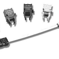
... STOP = 26.84 ns Fiber TM demo board for the transceiver shown in Figure 8. When using plastic fiber order the HFBR-0527P, and when using 200 µm HCS fixture in Figure 12 is also available as the HFBR-0319. The HFBR-0319 is a fully assembled test fixture. This test fix- ture adapts any fiber optic transceiver with a 1x9 footprint to test equipment with -5 V ECL inputs and outputs ...
Page 15
... TM fibers, digital data links that are comparable with the cost of shielded twisted pair wire can easily be implemented. The HFBR-15X7Z and HFBR- 25X6Z provide designers with a short haul data communi- cation solution that costs the same as shielded twisted pair wire, but this low cost fiber optic solution has none of the grounding and electromagnetic compatibility problems inherent in metallic cables ...
Page 16
... SOT-23 www.avagotech.com Part Number Quantity Vendor 1 C0805NPO500102JNE 3 Venkel C0805X7R500104KNE 12 Venkel C1812X7R500474KNE 1 Venkel TA016TCM106KBN 3 Venkel C0805COG500470JNE 1 Venkel C0805COG500121JNE 1 Venkel 74ACTQ00 1 National HFBR-1527Z 1 Avago HFBR-2526Z 1 Avago MC10H116FN 1 Motorola TL431CD 1 T.I. HF30ACB453215 1 TDK CR080510W4R7JT 2 Venkel CR080510W120JT 1 Venkel CR080510W150JT 1 Venkel CR080510W220JT 1 Venkel CR080510W510JT 4 Venkel CR080510W620JT 1 ...