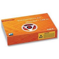
V850FX3-CANIT NEC, V850FX3-CANIT Datasheet - Page 16

V850FX3-CANIT
Manufacturer Part Number
V850FX3-CANIT
Description
STARTER KIT, 32BIT, CAN
Manufacturer
NEC
Datasheet
1.V850FX3-CANIT.pdf
(84 pages)
Specifications of V850FX3-CANIT
Svhc
No SVHC (18-Jun-2010)
Development Tool Type
Starter Kit
Kit Features
Easy To Use Device Demonstration Capabilities, TK-V850 Debugging, N-Wire Debugging
Mcu Supported Families
V850ES/Fx3
Silicon Manufacturer
NEC
Core Architecture
RISC
Kit Contents
Board
Features
N-Wire Debugging, Character LCD Module, USB Interface
V850ES/Fx3 – CAN it!
3.1 RESET button SW1
SW1 is a reset button. It activates the power on reset. It is connected to the reset input of the
V850ES/FG3 CPU module.
3.2 User button SW2
SW2 is a push button connecting V
to port P913 of the V850ES/FG3 device. The port may be programmed to generate interrupt INTP4. The
necessary initialisation for this purpose is described in the user’s manual of the V850ES/FG3 device. The
port is connected to a 4.7K pull down resistor.
3.3 User button SW3
SW3 is a push button connecting V
to port P914 of the V850ES/FG3 device. The port may be programmed to generate interrupt INTP5. The
necessary initialisation for this purpose is described in the user’s manual of the V850ES/FG3 device. The
port is connected to a 4.7K pull down resistor.
3.4 Configuration switch SW4
The different operation modes of the V850ES/Fx3 – CAN it! board can be set by SW4 switches S1-S4.
3.4.1 Operation mode selection SW4/S1
SW4 switch S1 controls the operation mode of the V850ES/Fx3 – CAN it! board. Setting SW4/S1 to ON
enables the TK-V850 On-Board debug function. Additional On-Board FLASH programming by using the
FPL software is supported in this mode.
Within normal operation mode (setting SW4/S1 to OFF) the user program stored in the internal FLASH
memory of V850ES/FG3 device is executed. Additional debugging via N-Wire interface and FLASH
programming via the PG-FP4 FLASH programmer is supported in this mode.
For more details on how to configure V850ES/Fx3 – CAN it! in order to use On-Chip debugging please
refer to CHAPTER 5, ON-CHIP DEBUGGING.
OFF
ON
SW4, S1
SW4
S1
S2
S3
S4
Table 1: Configuration switch SW4, factory settings
Table 2: Operation mode selection SW4/S1
User’s Manual U18560EE1V0UM00
CC
CC
Factory settings
TK-V850 debugging / FPL FLASH programming
to external interrupt input INTP4 of the microcontroller. This is equal
to external interrupt input INTP5 of the microcontroller. This is equal
OFF
OFF
OFF
OFF
Normal operation mode
Operation mode
Operation mode select
TK-V850 / FPL mode select
UART/ LIN mode selection
User switch
mode
Functionality
16


