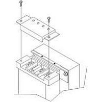
IP20 SOLA HEVI DUTY, IP20 Datasheet - Page 27

IP20
Manufacturer Part Number
IP20
Description
Fuse Cover Kit
Manufacturer
SOLA HEVI DUTY
Datasheet
1.RELAY_CARD-INT.pdf
(46 pages)
Specifications of IP20
Peak Reflow Compatible (260 C)
No
Kit Contents
2 Covers And Thread Forming Screws
Leaded Process Compatible
No
For Use With
SBE Fuse Block
Lead Free Status / RoHS Status
Lead free / RoHS Compliant
Available stocks
Company
Part Number
Manufacturer
Quantity
Price
Part Number:
IP2000-06
Manufacturer:
IR
Quantity:
20 000
Company:
Part Number:
IP2001
Manufacturer:
International Rectifier
Quantity:
10 000
Part Number:
IP2001
Manufacturer:
IR
Quantity:
20 000
Company:
Part Number:
IP2001PBF
Manufacturer:
International Rectifier
Quantity:
10 000
Company:
Part Number:
IP2001TR
Manufacturer:
IR
Quantity:
1 000
Company:
Part Number:
IP2001TR
Manufacturer:
International Rectifier
Quantity:
10 000
Part Number:
IP2001TR
Manufacturer:
IR
Quantity:
20 000
Company:
Part Number:
IP2001TRPBF
Manufacturer:
International Rectifier
Quantity:
10 000
Company:
Part Number:
IP2002
Manufacturer:
International Rectifier
Quantity:
10 000
Part Number:
IP2003
Manufacturer:
IR
Quantity:
20 000
Part Number:
IP2003AP
Manufacturer:
IR
Quantity:
20 000
9.0
9.1
9.2
9.3
9.4
O
Normal Mode Operation
During normal operation, mains power provides energy to the
UPS. The filters, power factor correction circuit and the inverter
process this power to provide computer grade power to connected
loads. The UPS maintains the batteries in a fully charged state.
The four green load level LEDs indicate an approximate level of
load in 25% increments. If the UPS becomes loaded beyond full
rating, the fifth (amber) LED indicator will illuminate and the
UPS will sound an audible alarm. The display template indicates
the percentage of load (10% of load shown in example) on the UPS
output.
Battery Mode Operation
Battery mode occurs in event of an extreme input voltage condition
or complete mains failure. The battery system supplies power
through the DC to DC converter to the inverter to generate power
for the connected load. During battery mode an alarm sounds
every 10 seconds. This will change to two beeps every 5 seconds
when the battery runs low (approximately 2 minutes remaining,
but this is user configurable). The AC Input LED will extinguish,
and the Battery LED will illuminate to warn that a mains problem
has occurred. Each battery level indicator represents a 20% capac-
ity level. As capacity decreases, fewer indicators remain illumi-
nated. Refer to 12.0 - Troubleshooting. For approximate battery
run times, refer to Table 6. These times are approximate, based on resistive load and an ambient
temperature of 25°C (77°F). To increase this time, turn off non-essential pieces of equipment (such as
idle computers and monitors) or add the optional external battery cabinet.
Bypass Mode Operation
Bypass mode occurs when the OFF button is pressed once while
the UPS is in Normal Mode. During bypass operation, mains
power provides energy to the UPS. The mains power bypasses the
inverter and provides power for the connected load.
The four green load level LEDs indicate an approximate level of
load in 25% increments. If the UPS becomes loaded beyond full
rating, the fifth (amber) LED indicator will illuminate and the
UPS will sound an audible alarm. The display template indicates
the percentage of load (26-50% of load shown in the example above) on the UPS output.
Battery Recharge Mode
Once mains power is restored, the UPS resumes normal operation. At this time, the Battery Charger
begins recharging.
!
PERATING
CAUTION
Turning OFF the UPS while in it is battery mode will cut off output power.
I
NSTRUCTIONS
21
Normal Mode Operation
Batteries at 100% Charge
Load at 10%
Battery Mode Operation
Batteries at 30% Charge
Load at 50%
AC INPUT
AC INPUT
AC
Operating Instructions
BATTERY
BAT
UPS ON
UPS ON
BYPASS
BYPASS


