IP20 SOLA HEVI DUTY, IP20 Datasheet - Page 17
IP20
Manufacturer Part Number
IP20
Description
Fuse Cover Kit
Manufacturer
SOLA HEVI DUTY
Datasheet
1.RELAY_CARD-INT.pdf
(46 pages)
Specifications of IP20
Peak Reflow Compatible (260 C)
No
Kit Contents
2 Covers And Thread Forming Screws
Leaded Process Compatible
No
For Use With
SBE Fuse Block
Lead Free Status / RoHS Status
Lead free / RoHS Compliant
Available stocks
Company
Part Number
Manufacturer
Quantity
Price

Part Number:
IP2000-06
Manufacturer:
IR
Quantity:
20 000
Company:
Part Number:
IP2001
Manufacturer:
International Rectifier
Quantity:
10 000
Part Number:
IP2001
Manufacturer:
IR
Quantity:
20 000
Company:
Part Number:
IP2001PBF
Manufacturer:
International Rectifier
Quantity:
10 000
Company:
Part Number:
IP2001TR
Manufacturer:
IR
Quantity:
1 000
Company:
Part Number:
IP2001TR
Manufacturer:
International Rectifier
Quantity:
10 000
Part Number:
IP2001TR
Manufacturer:
IR
Quantity:
20 000
Company:
Part Number:
IP2001TRPBF
Manufacturer:
International Rectifier
Quantity:
10 000
Company:
Part Number:
IP2002
Manufacturer:
International Rectifier
Quantity:
10 000
Part Number:
IP2003
Manufacturer:
IR
Quantity:
20 000
Part Number:
IP2003AP
Manufacturer:
IR
Quantity:
20 000


5.0
5.1
5.1.1
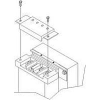
Figure 5
5.1.2
I
Do NOT attempt to start the UPS, turn on any circuit breaker or energize the input power until
instructed to do so in 6.0 - Initial Start-Up and Electrical Checks.
Visually inspect the UPS for freight damage. Report any damage to the carrier and your local dealer
or Sola/Hevi-Duty representative.
Install the S4K5U indoors in a controlled environment, where it cannot be accidentally turned off.
Place it where air flows unrestricted around the unit. The installation location must be free of water,
flammable liquids, gases, corrosives and conductive contaminants. Maintain a minimum clearance of
100mm (4 inches) in the front and rear of the UPS. Maintain an ambient temperature range of 0 to
40°C (32 -104°F).
Install the Main Cabinet
The S4K5U may be installed in either a tower configuration or in a rack, depending on available
space and use considerations. Determine the type of installation and follow the appropriate instruc-
tions in either 5.1.1 - Tower UPS Installation or 5.1.2 - Rack-Mount UPS Installation.
Tower UPS Installation
When using the S4K5U in a tower configuration, use the included support base (shown below, left) to
stabilize the UPS. If any external battery cabinets are added, they will include spacers to accommo-
date the additional cabinets (shown below, right).
Rack-Mount UPS Installation
When using the S4K5U in a rack-mount configuration, the UPS must be supported by a slide kit,
fixed rails or a shelf.
When using the optional Adjustable Rack Mount Kit, you will use the following instructions. The fig-
ures accompanying 5.1.3 - Installing the Adjustable Rack-Mount Kit—Sold Separately shows
the positioning of the rack-mounting brackets. Taking the internal batteries out of the UPS during
rack installation is recommended. This will make the UPS cabinet lighter and easier to handle.
NSTALLATION AND
!
!
Tower-use support bases, spacers for external battery cabinets
5U support base for S4K5U
End bases and 3U spacer
CAUTION
The UPS is heavy (see 13.0 - Specifications (Sechnische Daten)). Take
proper precautions when lifting or moving it.
NOTE
UPS operation in sustained temperatures above 25°C (77°F) reduces battery life.
This device is intended for use in an Installation Category II environment.
CAUTION
Only three (3) M4 screws are used on the side of the S4K5U where the Power Distribution Box
is located. The fourth mounting hole is above the Power Distribution Box and is not used.
3U
C
ONFIGURATION
11
Spacers added to support base
to accommodate additional battery cabinets
3U
3U
Installation and Configuration
2U
2U
2U
2U
Related parts for IP20
Image
Part Number
Description
Manufacturer
Datasheet
Request
R

Part Number:
Description:
Encapsulated/PC Board Transformer
Manufacturer:
SOLA HEVI DUTY
Datasheet:

Part Number:
Description:
Linear & Switching Power Supplies 250W 24V @ 10A
Manufacturer:
SOLA HEVI DUTY
Datasheet:

Part Number:
Description:
Surge Suppressors DIN Rail Sgl Pair TVSS 36V
Manufacturer:
SOLA HEVI DUTY
Datasheet:

Part Number:
Description:
Surge Suppressors Cat 5/6 POE mal-fem
Manufacturer:
SOLA HEVI DUTY
Datasheet:
Part Number:
Description:
Surge Suppressors 2 Pair data/signa l Protection36V
Manufacturer:
SOLA HEVI DUTY
Datasheet:
Part Number:
Description:
Surge Suppressors Cat 5/6 POE fem-fem
Manufacturer:
SOLA HEVI DUTY
Datasheet:

Part Number:
Description:
Surge Suppressors Base Connector STC-642 Series
Manufacturer:
SOLA HEVI DUTY
Datasheet:
Part Number:
Description:
Surge Suppressors CCTV Coax surge protection
Manufacturer:
SOLA HEVI DUTY
Datasheet:
Part Number:
Description:
Surge Suppressors CCTV Coax surge protection Isolated
Manufacturer:
SOLA HEVI DUTY
Datasheet:
Part Number:
Description:
Surge Suppressors DIN Rail Sgl Pair TVSS 22V
Manufacturer:
SOLA HEVI DUTY
Datasheet:

Part Number:
Description:
Surge Suppressors DIN Rail Sgl Pair TVSS 60V
Manufacturer:
SOLA HEVI DUTY

Part Number:
Description:
Surge Suppressors RJ-11 Telephone Surge Protection
Manufacturer:
SOLA HEVI DUTY
Datasheet:
Part Number:
Description:
Surge Suppressors 2 Pair data/signal Protection20V
Manufacturer:
SOLA HEVI DUTY
Datasheet:
Part Number:
Description:
Surge Suppressors DIN RAIL Kit PCB1B base
Manufacturer:
SOLA HEVI DUTY
Datasheet: