IP20 SOLA HEVI DUTY, IP20 Datasheet - Page 18
IP20
Manufacturer Part Number
IP20
Description
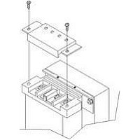
Fuse Cover Kit
Manufacturer
SOLA HEVI DUTY
Datasheet
1.RELAY_CARD-INT.pdf
(46 pages)
Specifications of IP20
Peak Reflow Compatible (260 C)
No
Kit Contents
2 Covers And Thread Forming Screws
Leaded Process Compatible
No
For Use With
SBE Fuse Block
Lead Free Status / RoHS Status
Lead free / RoHS Compliant
Available stocks
Company
Part Number
Manufacturer
Quantity
Price

Part Number:
IP2000-06
Manufacturer:
IR
Quantity:
20 000
Company:
Part Number:
IP2001
Manufacturer:
International Rectifier
Quantity:
10 000
Part Number:
IP2001
Manufacturer:
IR
Quantity:
20 000
Company:
Part Number:
IP2001PBF
Manufacturer:
International Rectifier
Quantity:
10 000
Company:
Part Number:
IP2001TR
Manufacturer:
IR
Quantity:
1 000
Company:
Part Number:
IP2001TR
Manufacturer:
International Rectifier
Quantity:
10 000
Part Number:
IP2001TR
Manufacturer:
IR
Quantity:
20 000
Company:
Part Number:
IP2001TRPBF
Manufacturer:
International Rectifier
Quantity:
10 000
Company:
Part Number:
IP2002
Manufacturer:
International Rectifier
Quantity:
10 000
Part Number:
IP2003
Manufacturer:
IR
Quantity:
20 000
Part Number:
IP2003AP
Manufacturer:
IR
Quantity:
20 000


5.1.3
Installing the Adjustable Rack-Mount Kit—Sold Separately
This kit contains parts needed to mount several different models of UPS and external battery cabi-
nets into EIA310-D standard four-post racks that are 18-32" deep (457-813mm). The weight limit per
pair of adjustable rack-mounting brackets is 91 kg (200lbs.).
Parts included are:
Tools needed for installation are:
The adjustable rack-mounting brackets (part # SRS18-32) feature retaining latches to prevent users
from inadvertently sliding the UPS or battery cabinet out of the rack.
To install the rack mount brackets:
1. Unpack two (2) rack-mounting bracket assemblies and
2. Determine the height position inside the rack enclosure
3. Install the rear member of each bracket assembly into the
!
Rear bracket members
Front bracket members
Inner bracket members
M4 x 8mm machine screws
M4 locking hex nuts
M5 x 16 mm machine screws
Grease packet.
• one Phillips screwdriver
• one 7mm wrench
mounting hardware from this kit. Bracket assemblies are
interchangeable between left-hand or right-hand.
Remove inner member of each bracket assembly as shown
at right by extending it to its outermost position, depress-
ing the retaining latch and then pulling the inner member
out of the bracket assembly.
where you want to mount the UPS or battery cabinet.
rack enclosure with two (2) M5 screws provided in this kit
(see figure at right). The return flanges on the bracket
assembly fit to the inside of rack mounting rails. Insert
screws loosely (finger-tight) into the top and bottom holes of
the return flange on the rear member. Extend the bracket
assembly by sliding the front member forward until it
touches the front rack mounting rail. Insert two (2) M5
screws loosely (finger-tight) into the top and bottom holes of
the return flange on each front member. Make sure that the
bracket assemblies are at the same mounting height on all
four (4) rack mounting rails.
CAUTION
Reduce the risk of tipping the rack enclosure by
placing the UPS or battery cabinet in the lowest
possible rack position.
Item
Quantity
16
12
2
2
2
8
1
12
M5 screws
Front rack
mounting rails
Inner
members
Retaining
Latches
Installation and Configuration
Rear rack
mounting
rails
Front
members
M5 screws
Return
flanges
Related parts for IP20
Image
Part Number
Description
Manufacturer
Datasheet
Request
R

Part Number:
Description:
Encapsulated/PC Board Transformer
Manufacturer:
SOLA HEVI DUTY
Datasheet:

Part Number:
Description:
Linear & Switching Power Supplies 250W 24V @ 10A
Manufacturer:
SOLA HEVI DUTY
Datasheet:

Part Number:
Description:
Surge Suppressors DIN Rail Sgl Pair TVSS 36V
Manufacturer:
SOLA HEVI DUTY
Datasheet:

Part Number:
Description:
Surge Suppressors Cat 5/6 POE mal-fem
Manufacturer:
SOLA HEVI DUTY
Datasheet:
Part Number:
Description:
Surge Suppressors 2 Pair data/signa l Protection36V
Manufacturer:
SOLA HEVI DUTY
Datasheet:
Part Number:
Description:
Surge Suppressors Cat 5/6 POE fem-fem
Manufacturer:
SOLA HEVI DUTY
Datasheet:

Part Number:
Description:
Surge Suppressors Base Connector STC-642 Series
Manufacturer:
SOLA HEVI DUTY
Datasheet:
Part Number:
Description:
Surge Suppressors CCTV Coax surge protection
Manufacturer:
SOLA HEVI DUTY
Datasheet:
Part Number:
Description:
Surge Suppressors CCTV Coax surge protection Isolated
Manufacturer:
SOLA HEVI DUTY
Datasheet:
Part Number:
Description:
Surge Suppressors DIN Rail Sgl Pair TVSS 22V
Manufacturer:
SOLA HEVI DUTY
Datasheet:

Part Number:
Description:
Surge Suppressors DIN Rail Sgl Pair TVSS 60V
Manufacturer:
SOLA HEVI DUTY

Part Number:
Description:
Surge Suppressors RJ-11 Telephone Surge Protection
Manufacturer:
SOLA HEVI DUTY
Datasheet:
Part Number:
Description:
Surge Suppressors 2 Pair data/signal Protection20V
Manufacturer:
SOLA HEVI DUTY
Datasheet:
Part Number:
Description:
Surge Suppressors DIN RAIL Kit PCB1B base
Manufacturer:
SOLA HEVI DUTY
Datasheet: