IP20 SOLA HEVI DUTY, IP20 Datasheet - Page 19
IP20
Manufacturer Part Number
IP20
Description
Fuse Cover Kit
Manufacturer
SOLA HEVI DUTY
Datasheet
1.RELAY_CARD-INT.pdf
(46 pages)
Specifications of IP20
Peak Reflow Compatible (260 C)
No
Kit Contents
2 Covers And Thread Forming Screws
Leaded Process Compatible
No
For Use With
SBE Fuse Block
Lead Free Status / RoHS Status
Lead free / RoHS Compliant
Available stocks
Company
Part Number
Manufacturer
Quantity
Price

Part Number:
IP2000-06
Manufacturer:
IR
Quantity:
20 000
Company:
Part Number:
IP2001
Manufacturer:
International Rectifier
Quantity:
10 000
Part Number:
IP2001
Manufacturer:
IR
Quantity:
20 000
Company:
Part Number:
IP2001PBF
Manufacturer:
International Rectifier
Quantity:
10 000
Company:
Part Number:
IP2001TR
Manufacturer:
IR
Quantity:
1 000
Company:
Part Number:
IP2001TR
Manufacturer:
International Rectifier
Quantity:
10 000
Part Number:
IP2001TR
Manufacturer:
IR
Quantity:
20 000
Company:
Part Number:
IP2001TRPBF
Manufacturer:
International Rectifier
Quantity:
10 000
Company:
Part Number:
IP2002
Manufacturer:
International Rectifier
Quantity:
10 000
Part Number:
IP2003
Manufacturer:
IR
Quantity:
20 000
Part Number:
IP2003AP
Manufacturer:
IR
Quantity:
20 000


6.
4. Get eight (8) M4 screws and eight (8) M4 nuts from the
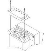
5. Prepare the UPS or battery cabinet (the “equipment”) for
6. Open the grease packet provided in the kit. Apply a bead of
7. Insert the equipment, with inner members attached in
8. Secure the front of the equipment to the rack mounting rails
!
hardware pack in this kit. Each nut has a locking, nylon
insert that begins gripping the screw when it is halfway
tight. Make sure to tighten the nut and screw completely to
ensure locking action. Fasten the rear member and the front
member together using (4) screws and (4) nuts per bracket
assembly as shown in at right. For maximum support, insert
fasteners for each bracket assembly as far apart as possible,
depending on rack depth, while still joining both members
(see figures at right). Check alignment of bracket assemblies
and TIGHTEN ALL SCREWS FROM Steps 2 and 3.
rack mounting by following instructions in the equipment’s
user manual. The equipment may require additional parts to
be added or parts to be removed for rack mounting. After it is
prepared, lay the equipment in rack-mounting position.
Fasten the inner members from Step 1 to the equipment on
both sides as shown at right with eight (8) M4 screws
provided in the kit. Make sure retaining latch is near the rear
of the equipment as shown (see figure at right).
grease 25mm (1") long at four (4) places inside the bottom,
curved tracks of the front members as shown below right. The
grease will allow the equipment to slide into the bracket
assemblies more easily.
Step 5, into the bracket assemblies by inserting the top and
bottom edges of the inner members into the top and bottom
curved tracks of the front members and sliding the
equipment into the rack (see figure at right). Ends of inner
members are tapered to allow the rear of the equipment to be
angled upward before insertion, if space allows.
Then the rear, bottom edges of the inner members can be
placed into the front edge of the bottom tracks and the front
of the equipment can be tipped up so they are level to insert
the top edges of the inner members before sliding the equip-
ment into the rack (see figure below right). The equipment
should move smoothly into the bracket assemblies. If it does
not, recheck the alignment of the front and rear members
from Steps 2 and 3.
to prevent the equipment from sliding out of position. If
securing holes are provided on the front of the equipment
that align with the center holes on the return flange of the
front members, you can use the four (4) extra M5 screws
provided in the kit to secure the equipment. Otherwise, the
equipment should be secured to the front of the rack with
four (4) customer-supplied fasteners.
CAUTION
Lifting equipment into the rack may be a two-person
job, depending on the weight of the equipment. Sola/
Hevi-Duty recommends taking the internal batteries
out of the UPS during rack installation. This will
make the UPS cabinet lighter and easier to handle.
The S4K5U weighs 67kg (151lb). For the battery
cabinet’s weight, see the unit’s user manual.
13
Insert the UPS into the front
members, lift the front ...
UPS or
battery
cabinet
M4 screws
Front
813mm
(32") rack
depth
M4 nuts
M4 nuts
457mm
(18")
rack
depth
Installation and Configuration
M4 screws
UPS or battery
cabinet
Apply
grease
Retaining latch
M4
screws
into the rack.
... and push it
M4 nuts
M4
screws
M4 nuts
Apply
grease
(inside)
Related parts for IP20
Image
Part Number
Description
Manufacturer
Datasheet
Request
R

Part Number:
Description:
Encapsulated/PC Board Transformer
Manufacturer:
SOLA HEVI DUTY
Datasheet:

Part Number:
Description:
Linear & Switching Power Supplies 250W 24V @ 10A
Manufacturer:
SOLA HEVI DUTY
Datasheet:

Part Number:
Description:
Surge Suppressors DIN Rail Sgl Pair TVSS 36V
Manufacturer:
SOLA HEVI DUTY
Datasheet:

Part Number:
Description:
Surge Suppressors Cat 5/6 POE mal-fem
Manufacturer:
SOLA HEVI DUTY
Datasheet:
Part Number:
Description:
Surge Suppressors 2 Pair data/signa l Protection36V
Manufacturer:
SOLA HEVI DUTY
Datasheet:
Part Number:
Description:
Surge Suppressors Cat 5/6 POE fem-fem
Manufacturer:
SOLA HEVI DUTY
Datasheet:

Part Number:
Description:
Surge Suppressors Base Connector STC-642 Series
Manufacturer:
SOLA HEVI DUTY
Datasheet:
Part Number:
Description:
Surge Suppressors CCTV Coax surge protection
Manufacturer:
SOLA HEVI DUTY
Datasheet:
Part Number:
Description:
Surge Suppressors CCTV Coax surge protection Isolated
Manufacturer:
SOLA HEVI DUTY
Datasheet:
Part Number:
Description:
Surge Suppressors DIN Rail Sgl Pair TVSS 22V
Manufacturer:
SOLA HEVI DUTY
Datasheet:

Part Number:
Description:
Surge Suppressors DIN Rail Sgl Pair TVSS 60V
Manufacturer:
SOLA HEVI DUTY

Part Number:
Description:
Surge Suppressors RJ-11 Telephone Surge Protection
Manufacturer:
SOLA HEVI DUTY
Datasheet:
Part Number:
Description:
Surge Suppressors 2 Pair data/signal Protection20V
Manufacturer:
SOLA HEVI DUTY
Datasheet:
Part Number:
Description:
Surge Suppressors DIN RAIL Kit PCB1B base
Manufacturer:
SOLA HEVI DUTY
Datasheet: