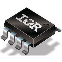
IRF7807ZPBF International Rectifier, IRF7807ZPBF Datasheet - Page 6

IRF7807ZPBF
Manufacturer Part Number
IRF7807ZPBF
Description
N CHANNEL MOSFET, 30V, 11A, SOIC
Manufacturer
International Rectifier
Type
Power MOSFETr
Datasheet
1.IRF7807ZPBF.pdf
(10 pages)
Specifications of IRF7807ZPBF
Transistor Polarity
N Channel
Continuous Drain Current Id
11A
Drain Source Voltage Vds
30V
On Resistance Rds(on)
13.8mohm
Rds(on) Test Voltage Vgs
10V
Threshold Voltage Vgs Typ
1.8V
Configuration
Single Quad Drain Triple Source
Resistance Drain-source Rds (on)
18.2 mOhms
Drain-source Breakdown Voltage
30 V
Gate-source Breakdown Voltage
20 V
Continuous Drain Current
11 A
Power Dissipation
2.5 W
Maximum Operating Temperature
+ 150 C
Mounting Style
SMD/SMT
Package / Case
SOIC-8
Fall Time
3.1 ns
Gate Charge Qg
7.2 nC
Minimum Operating Temperature
- 55 C
Rise Time
6.2 ns
Number Of Elements
1
Polarity
N
Channel Mode
Enhancement
Drain-source On-res
0.0138Ohm
Drain-source On-volt
30V
Gate-source Voltage (max)
±20V
Operating Temp Range
-55C to 150C
Operating Temperature Classification
Military
Mounting
Surface Mount
Pin Count
8
Package Type
SOIC
Lead Free Status / RoHS Status
Lead free / RoHS Compliant
Lead Free Status / RoHS Status
Lead free / RoHS Compliant
Fig 12a. Unclamped Inductive Test Circuit
6
Fig 12b. Unclamped Inductive Waveforms
Fig 13. Gate Charge Test Circuit
I
AS
12V
V
GS
R G
20V
Same Type as D.U.T.
V
V DS
GS
Current Regulator
.2µF
t p
50KΩ
3mA
I AS
Current Sampling Resistors
D.U.T
t p
.3µF
0.01 Ω
L
I
G
D.U.T.
15V
I
V
D
(BR)DSS
DRIVER
+
-
V
+
-
DS
V DD
A
300
250
200
150
100
50
90%
V
10%
0
V
Fig 14a. Switching Time Test Circuit
DS
Fig 14b. Switching Time Waveforms
25
GS
Fig 12c. Maximum Avalanche Energy
Starting T J , Junction Temperature (°C)
t
d(on)
50
Duty Factor < 0.1%
Pulse Width < 1µs
Vs. Drain Current
V
GS
t
r
75
V
DS
t
100
d(off)
www.irf.com
D.U.T
L
t
D
f
125
V
DD
+
-
150


