T1611100 Red Lion Controls, T1611100 Datasheet - Page 4
T1611100
Manufacturer Part Number
T1611100
Description
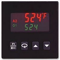
PID TEMPERATURE CONTROLLER, 3RELAYS
Manufacturer
Red Lion Controls
Type
Temperaturer
Specifications of T1611100
Thermocouple Type
T, E, J, K, R, S, B, N, C, Linear MV
Operating Temperature Max
50°C
Operating Temperature Min
0°C
Output Voltage Max
250VAC
Output Voltage Min
30VDC
Accuracy
0.3%
Approval
RoHS Compliant
Brand/series
T16 Series
Contact Form
SPST
Dimensions
49.5mmW×49.5mmH×115.3mmD
Enclosure Rating
IP65
Input Type
RTD/Thermocouple
Ip Rating
IP65
Memory
EEPROM
Mounting Type
Panel
Output Type
Relay
Power, Rating
8 VA
Primary Type
Controller
Special Features
EEPROM
Standards
cURus, CE
Termination
Screw
Voltage, Supply
85 to 250 VAC
Lead Free Status / Rohs Status
RoHS Compliant part


EMC INSTALLATION GUIDELINES
Electromagnetic Interference (EMI), proper installation and wiring methods
must be followed to ensure electromagnetic compatibility (EMC) in each
application. The type of the electrical noise, source or coupling method into the
controller may be different for various installations. The controller becomes
more immune to EMI with fewer I/O connections. Cable length, routing, and
shield termination are very important and can mean the difference between a
successful or troublesome installation. Listed are some EMC guidelines for
successful installation in an industrial environment.
1. The controller should be mounted in a metal enclosure that is properly
2. Use shielded (screened) cables for all Signal and Control inputs. The shield
3. Never run Signal or Control cables in the same conduit or raceway with AC
Although this controller is designed with a high degree of immunity to
connected to protective earth.
(screen) pigtail connection should be made as short as possible. The
connection point for the shield depends somewhat upon the application.
Listed below are the recommended methods of connecting the shield, in order
of their effectiveness.
a. Connect the shield only at the panel where the controller is mounted to
b. Connect the shield to earth ground at both ends of the cable, usually when
c. Connect the shield to common of the controller and leave the other end of
power lines, conductors feeding motors, solenoids, SCR controls, and
heaters, etc. The cables should be run through metal conduit that is properly
grounded. This is especially useful in applications where cable runs are long
and portable two-way radios are used in close proximity or if the installation
is near a commercial radio transmitter.
earth ground (protective earth).
the noise source frequency is more than 1 MHz.
the shield unconnected and insulated from earth ground.
BLOCK DIAGRAM
4
4. Signal or Control cables within an enclosure should be routed as far away as
5. In extremely high EMI environments, the use of external EMI suppression
6. Long cable runs are more susceptible to EMI pickup than short cable runs.
7. Switching of inductive loads produces high EMI. Use of snubbers across
possible from contactors, control relays, transformers, and other noisy
components.
devices, such as ferrite suppression cores, is effective. Install them on Signal
and Control cables as close to the controller as possible. Loop the cable
through the core several times or use multiple cores on each cable for
additional protection. Install line filters on the power input cable to the
controller to suppress power line interference. Install them near the power
entry point of the enclosure. The following EMI suppression devices (or
equivalent) are recommended:
Ferrite Suppression Cores for Signal and Control cables:
Line Filters for input power cables:
Note: Reference manufacturer’s instructions when installing a line filter.
Therefore, keep cable runs as short as possible.
inductive loads suppresses EMI.
Snubber: Red Lion Controls # SNUB0000.
Fair-Rite # 0443167251 (Red Lion Controls # FCOR0000)
TDK # ZCAT3035-1330A
Steward # 28B2029-0A0
Schaffner # FN610-1/07 (Red Lion Controls # LFIL0000)
Schaffner # FN670-1.8/07
Corcom # 1 VR3
*AL1 becomes main control O1, if selected for heating in the
analog out models.
Related parts for T1611100
Image
Part Number
Description
Manufacturer
Datasheet
Request
R

Part Number:
Description:
DC, W/Relay Output
Manufacturer:
Red Lion Controls
Datasheet:
Part Number:
Description:
DC, W/Relay Out, 2 Alarms, And User Input
Manufacturer:
Red Lion Controls
Datasheet:
Part Number:
Description:
W/Solid State Out, 2 Alarms, And User Input
Manufacturer:
Red Lion Controls
Datasheet:
Part Number:
Description:
DC, W/Analog Out, 2 Alarms, And User Input
Manufacturer:
Red Lion Controls
Datasheet:
Part Number:
Description:
Counter
Manufacturer:
Red Lion Controls
Datasheet:
Part Number:
Description:
Miniature Length Sensor
Manufacturer:
Red Lion Controls
Datasheet:
Part Number:
Description:
Model Lsc - Single Channel Output Length Sensor
Manufacturer:
Red Lion Controls
Datasheet: