XS1M18MA230 SQUARE D, XS1M18MA230 Datasheet - Page 78
XS1M18MA230
Manufacturer Part Number
XS1M18MA230
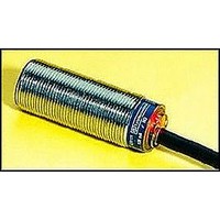
Description
Inductive Proximity Sensor
Manufacturer
SQUARE D
Datasheet
1.XS1M18KP340.pdf
(172 pages)
Specifications of XS1M18MA230
Sensor Input
Inductive
Sensing Range
5mm
Supply Voltage Range Ac
24V To 240V
Sensor Output
NO
Peak Reflow Compatible (260 C)
No
Sensor Housing
Cylindrical
Sensing Range Max
5mm
Output Type
NO
Lead Free Status / RoHS Status
Contains lead / RoHS non-compliant


Proximity Sensors
XS Inductive Sensors
Cubic Block Style, 26 x 26 mm and 40 x 40 mm Square, DC
274
Dual Dimensions inches
Ø3
1.02
1.18
26
30
1.57
1.57
40
40
1.73
1.22
1.73
44
.98
31
25
2.09
2.16
44
53
55
LED
Ø5.3x8
LED
LED
mm
Ø4.2
Ø5.3
Ø5.3x8
=
1.57
1.18
40
30
=
1.02
26
=
=
1.57
40
=
=
Ø5.3
XS Inductive Sensors / Cubic Block Style, 26 x 26 mm and 40 x 40 mm Square, DC
Features
• Compact cubed body style in rugged PBT plastic
• Flush and Non-flush mountable
• Comparable sensing distance to Limit Switch style in half the body size
• Mounting bracket included with each sensor
• Elbow bracket provides interchangeability with Limit Switch style sensor, and enables
• Molded cable or molded cable with Micro connector pigtail at 0.8 m or 0.15 m length
q
Minimum Mounting Clearances
Description
26 mm x 26 mm
DC, Flush Mountable
2 Meter (6’) Cable q
26 x 26
26 x 26
26 x 26
0.8 m (2.6 ft) Pigtail with 4 Pin Micro Connector q
26 x 26
26 x 26
26 x 26
0.15 m (5.9 ft) Pigtail with 4 Pin Micro Connector q
26 x 26
DC, Non-Flush Mountable
2 Meter (6’) Cable q
26 x 26
26 x 26
0.8 m (2.6 ft) Pigtail with 4 Pin Micro Connector q
26 x 26
26 x 26
40 mm x 40 mm
DC, Flush Mountable
2 Meter (6’) Cable q
40 x 40
40 x 40
40 x 40
0.8 m (2.6 ft) Pigtail with 4 Pin Micro Connector q
40 x 40
40 x 40
40 x 40
0.15 m (5.9 ft) Pigtail with 4 Pin Micro Connector q
40 x 40
DC, Non-Flush Mountable
2 Meter (6’) Cable q
40 x 40
40 x 40
0.8 m (2.6 ft) Pigtail with 4 Pin Micro Connector q
40 x 40
40 x 40
XS7T2 Shielded
XS7T4 Non-shielded
XS7T4 Shielded
XS8T4 Non-shielded
multiple positioning of sensing face
See p. 518 for matching connector cables
Side by Side
E1
©1997
Nominal
Sensing
Distance
10 mm
10 mm
10 mm
10 mm
10 mm
10 mm
10 mm
15 mm
15 mm
15 mm
15 mm
15 mm
15 mm
15 mm
15 mm
15 mm
15 mm
15 mm
20 mm
20 mm
20 mm
20 mm
-
2002 Schneider Electric All Rights Reserved
Circuit
Type
2 wire
PNP
NPN
2 wire
PNP
NPN
2 wire
PNP
NPN
PNP
NPN
2 wire
PNP
NPN
2 wire
PNP
NPN
2 wire
PNP
NPN
PNP
NPN
Face to Face
E1
IN
0.98
1.57
1.49
2.36
E2
Output
Mode
N.O.
N.O. + N.C.
N.O. + N.C.
N.O.
N.O. + N.C.
N.O. + N.C.
N.O.
N.O. + N.C.
N.O. + N.C.
N.O. + N.C.
N.O. + N.C.
N.O.
N.O. + N.C.
N.O. + N.C.
N.O.
N.O. + N.C.
N.O. + N.C.
N.O.
N.O. + N.C.
N.O. + N.C.
N.O. + N.C.
N.O. + N.C.
mm
25
40
38
60
E2
IN
4.32
4.71
4.72
6.29
Voltage
Range
12–48 Vdc
12–48 Vdc
12–48 Vdc
12–48 Vdc
12–48 Vdc
12–48 Vdc
12–48 Vdc
12–48 Vdc
12–48 Vdc
12–48 Vdc
12–48 Vdc
12–48 Vdc
12–48 Vdc
12–48 Vdc
12–48 Vdc
12–48 Vdc
12–48 Vdc
12–48 Vdc
12–48 Vdc
12–48 Vdc
12–48 Vdc
12–48 Vdc
mm
110
120
120
160
Facing a Metal Object
Voltage
Drop
Max.
5.2 V
2 V
2 V
5.2 V
2 V
2 V
5.2 V
2 V
2 V
2 V
2 V
5.2 V
2 V
2 V
5.2 V
2 V
2 V
5.2 V
2 V
2 V
2 V
2 V
E3
IN
1.18
1.77
1.77
2.36
E3
Load
Current
Max.
100 mA
200 mA
200 mA
100 mA
200 mA
200 mA
100 mA
200 mA
200 mA
200 mA
200 mA
100 mA
200 mA
200 mA
100 mA
200 mA
200 mA
100 mA
200 mA
200 mA
200 mA
200 mA
mm
30
45
45
60
Operating
Frequency
Max.
100 Hz
1000 Hz
1000 Hz
100 Hz
1000 Hz
1000 Hz
100 Hz
500 Hz
500 Hz
500 Hz
500 Hz
150 Hz
1000 Hz
1000 Hz
150 Hz
1000 Hz
1000 Hz
150 Hz
1000 Hz
1000 Hz
1000 Hz
1000 Hz
D1
IN
1.02
1.57
3.07
4.72
Mounted in a Metal Support
mm
120
26
40
78
Catalog Number
XS7T2DA210
XS7T2PC440
XS7T2NC440
XS7T2DA214LD
XS7T2PC440LD
XS7T2NC440LD
XS7T2DA214LD01
XS8T2PC440
XS8T2NC440
XS8T2PC440LD
XS8T2NC440LD
XS7T4DA210
XS7T4PC440
XS7T4NC440
XS7T4DA214LD
XS7T4PC440LD
XS7T4NC440LD
XS7T4DA214LD01
XS8T4PC440
XS8T4NC440
XS8T4PC440LD
XS8T4NC440LD
D1
H
IN
1.02
1.57
0
0
mm
26
40
0
0
10/02
Related parts for XS1M18MA230
Image
Part Number
Description
Manufacturer
Datasheet
Request
R


Part Number:
Description:
Pushbutton, Non-Illum'd Red "STOP", Momentary, 1NO-1NC, Square 30mm, 10A, 600V
Manufacturer:
SQUARE D
Datasheet:

Part Number:
Description:
KITS,TWIDO? PROGRAMMABLE CONTROLLERS,KITS,TWIDOPACK STARTER KIT - ADVANCED LEVEL,PROGRAMMABLE CONTROLLERS,TWIDO? PROGRAMMABLE CONTROLLERS ,SQUARE D
Manufacturer:
SQUARE D

Part Number:
Description:
LAMPS,INDICATOR,STACKABLE,LAMPS, STACKABLE INDICATOR,VISUAL INDICATING SIGNALS,XVB SERIES INDICATING BANKS ,SQUARE D
Manufacturer:
SQUARE D
Part Number:
Description:
LAMPS,INDICATOR,STACKABLE,LAMPS, STACKABLE INDICATOR,VISUAL INDICATING SIGNALS,XVB SERIES INDICATING BANKS ,SQUARE D
Manufacturer:
SQUARE D
Datasheet:
Part Number:
Description:
I/O EXTENDER MODULE 4 D IN & 2 D OUTPUT
Manufacturer:
SQUARE D
Datasheet:
Part Number:
Description:
CB ACCESSORY, UNDERVOLTAGE TRIP 48V DC
Manufacturer:
SQUARE D
Datasheet: