XS1M18MA230 SQUARE D, XS1M18MA230 Datasheet - Page 164
XS1M18MA230
Manufacturer Part Number
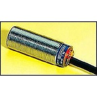
XS1M18MA230
Description
Inductive Proximity Sensor
Manufacturer
SQUARE D
Datasheet
1.XS1M18KP340.pdf
(172 pages)
Specifications of XS1M18MA230
Sensor Input
Inductive
Sensing Range
5mm
Supply Voltage Range Ac
24V To 240V
Sensor Output
NO
Peak Reflow Compatible (260 C)
No
Sensor Housing
Cylindrical
Sensing Range Max
5mm
Output Type
NO
Lead Free Status / RoHS Status
Contains lead / RoHS non-compliant


Proximity Sensors
PLC Compatibility
360
Rb
Sensor
Rin
V supply
PLC
PLC Compatibility
In order for a solid state, 2 wire, AC sensor to be directly compatible with a PLC, two conditions
have to be met:
1. Leakage current: (I off) less than 1.7 mA (Off state)
2. Load current: greater than the sensor minimum load current (ON state). Typical PLC
input currents (load current, I load) are 12-16 mA. Typical values for PLC input resistance (Rin)
are: 7.5-10 kΩ.
For sensors which do not meet both of the requirements, a Bleeder Resistor (Rb) has to be
wired in parallel with the load.
For each of the two situations, the Bleeder Resistor parameters have to be calculated as shown
below. The smaller value should be selected for the application.
1. Rb =
Where:
Example:
I off
Vo max
Rin
Typical examples for Telemecanique TSX DET input modules:
For I off = 3.5 mA
For I off = 7 mA
2.
Example:
I min
Vs
Rin
Typical examples using TSX programmable controllers:
For I min = 20 mA
For I min = 30 mA
NOTE: All DC 3 wire sensors are PLC compatible.
Rb =
I off (Rin) – Vo max
Vo max
Rin
Vs
Pb
©
= 3.5 mA
= 20 V
= 6.5 kΩ
= 30 mA
= 120 V
= 7 kΩ
Rin x Vo Max
I off (Rin) – Vo max
1997-2002 Schneider Electric All Rights Reserved
Rin x Vo Max
= PLC input maximum OFF voltage (20-40 Vac)
= PLC input resistance
= Line voltage
= Minimum Bleeder Resistor power rating
❊
❊
Pb = Vs
TSX DET 1604
47 kΩ/0.5 W
4.7 kΩ/3 W
TSX DET 1604
64 kΩ/0.5 W
8.7 kΩ/2 W
Rb
Pb = Vs
2
Rb
2
TSX DET 0804
—
12 kΩ/1.5 W
TSX DET 0804
24 kΩ/1 W
8.7 kΩ/2 W
10/02
Related parts for XS1M18MA230
Image
Part Number
Description
Manufacturer
Datasheet
Request
R


Part Number:
Description:
Pushbutton, Non-Illum'd Red "STOP", Momentary, 1NO-1NC, Square 30mm, 10A, 600V
Manufacturer:
SQUARE D
Datasheet:

Part Number:
Description:
KITS,TWIDO? PROGRAMMABLE CONTROLLERS,KITS,TWIDOPACK STARTER KIT - ADVANCED LEVEL,PROGRAMMABLE CONTROLLERS,TWIDO? PROGRAMMABLE CONTROLLERS ,SQUARE D
Manufacturer:
SQUARE D

Part Number:
Description:
LAMPS,INDICATOR,STACKABLE,LAMPS, STACKABLE INDICATOR,VISUAL INDICATING SIGNALS,XVB SERIES INDICATING BANKS ,SQUARE D
Manufacturer:
SQUARE D
Part Number:
Description:
LAMPS,INDICATOR,STACKABLE,LAMPS, STACKABLE INDICATOR,VISUAL INDICATING SIGNALS,XVB SERIES INDICATING BANKS ,SQUARE D
Manufacturer:
SQUARE D
Datasheet:
Part Number:
Description:
I/O EXTENDER MODULE 4 D IN & 2 D OUTPUT
Manufacturer:
SQUARE D
Datasheet:
Part Number:
Description:
CB ACCESSORY, UNDERVOLTAGE TRIP 48V DC
Manufacturer:
SQUARE D
Datasheet: