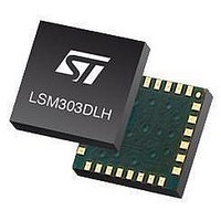
LSM303DLHTR STMicroelectronics, LSM303DLHTR Datasheet - Page 41

LSM303DLHTR
Manufacturer Part Number
LSM303DLHTR
Description
IC ACCELEROMETER 3AXIS 3D 28LGA
Manufacturer
STMicroelectronics
Datasheet
1.STEVAL-MKI063V1.pdf
(47 pages)
Specifications of LSM303DLHTR
Output Type
Digital - I²C
Sensor Type
Accelerometer and Magnetometer
Sensing Axis
Triple
Acceleration
2 g, 4 g, 8 g
Sensitivity
1 mg/digit, 2 mg/digit, 3.9 mg/digit
Package / Case
LGA-28L
Digital Output - Number Of Bits
16 bit
Supply Voltage (max)
3.3 V
Supply Voltage (min)
2.5 V
Maximum Operating Temperature
+ 85 C
Minimum Operating Temperature
- 30 C
Digital Output - Bus Interface
I2C
For Use With
497-10689 - BOARD ADAPTER LSM303DLH DIL24
Lead Free Status / RoHS Status
Lead free / RoHS Compliant
Other names
497-10765-2
LSM303DLHTR
LSM303DLHTR
Available stocks
Company
Part Number
Manufacturer
Quantity
Price
Company:
Part Number:
LSM303DLHTR
Manufacturer:
ST
Quantity:
8 295
Company:
Part Number:
LSM303DLHTR-SMJ
Manufacturer:
ST
Quantity:
8 305
LSM303DLH
9.2.4
the first bit of the data stream. The number in parentheses indicates the default value of that
bit.
Table 63.
Table 64.
Table 65.
OUT_X_M (03-04h)
The data output X registers are two 8-bit registers, data output register H and data output
register L. These registers store the measurement result from channel X.
Data output X register H contains the MSB from the measurement result, and data output X
register L contains the LSB from the measurement result.
The value stored in these two registers is a 16-bit value in 2’s complement form, whose
range is 0xF800 to 0x07FF. DXRH0 through DXRH7 and DXRL0 through DXRL7 indicate bit
locations, with DXRH and DXRL denoting the bits that are in the data output X registers.
DXRH7 and DXRL7 denote the first bit of the data stream.
In the event the ADC reading overflows or underflows for the given channel, or if there is a
math overflow during the bias measurement, this data register will contain the value -4096 in
2’s complement form. This register value clears after the next valid measurement is made.
Table 66.
The content of this register is the MSB magnetic field data for X-axis.
MR7 to MR2
MR1 to MR0
DXRH7
MD1
0
0
1
1
0
MD0
MR_REG
MR_REG description
Magnetic sensor operating mode
OUTXH_M register
0
1
0
1
DXRH6
These bits must be cleared for correct operation
Mode select bits. These bits select the operation mode of this device.
0
Continuous-conversion mode: the device continuously performs conversions
and places the result in the data register. RDY goes high when new data is
placed in all three registers. After a power-on or a write to the mode or
configuration register, the first measurement set is available from all three data
output registers after a period of 2/fDO, and subsequent measurements are
available at a frequency of fDO, where fDO is the frequency of data output.
Single-conversion mode: the device performs a single measurement, sets RDY
high and returns to sleep mode. Mode register returns to sleep mode bit values.
The measurement remains in the data output register and RDY remains high
until the data output register is read or another conversion is performed.
--
Sleep mode. Device is placed in sleep mode
DXRH5
0
Doc ID 16941 Rev 1
DXRH4
0
DXRH3
0
Mode
DXRH2
0
Registers description
DXRH1
MD1
DXRH0
MD0
41/47


