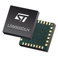
LSM303DLHTR STMicroelectronics, LSM303DLHTR Datasheet - Page 21

LSM303DLHTR
Manufacturer Part Number
LSM303DLHTR
Description
IC ACCELEROMETER 3AXIS 3D 28LGA
Manufacturer
STMicroelectronics
Datasheet
1.STEVAL-MKI063V1.pdf
(47 pages)
Specifications of LSM303DLHTR
Output Type
Digital - I²C
Sensor Type
Accelerometer and Magnetometer
Sensing Axis
Triple
Acceleration
2 g, 4 g, 8 g
Sensitivity
1 mg/digit, 2 mg/digit, 3.9 mg/digit
Package / Case
LGA-28L
Digital Output - Number Of Bits
16 bit
Supply Voltage (max)
3.3 V
Supply Voltage (min)
2.5 V
Maximum Operating Temperature
+ 85 C
Minimum Operating Temperature
- 30 C
Digital Output - Bus Interface
I2C
For Use With
497-10689 - BOARD ADAPTER LSM303DLH DIL24
Lead Free Status / RoHS Status
Lead free / RoHS Compliant
Other names
497-10765-2
LSM303DLHTR
LSM303DLHTR
Available stocks
Company
Part Number
Manufacturer
Quantity
Price
Company:
Part Number:
LSM303DLHTR
Manufacturer:
ST
Quantity:
8 295
Company:
Part Number:
LSM303DLHTR-SMJ
Manufacturer:
ST
Quantity:
8 305
LSM303DLH
6.1
6.2
6.3
6.4
External capacitors
The C1 and C2 external capacitors should have a low SR value ceramic type construction.
Reservoir capacitor C1 is nominally 4.7 µF in capacitance, with the set/reset capacitor C2
nominally 0.22 µF in capacitance.
The device core is supplied through the Vdd line. Power supply decoupling capacitors
(C4=100 nF ceramic, C3=10 µF Al) should be placed as near as possible to the supply pin
of the device (common design practice). All the voltage and ground supplies must be
present at the same time to obtain proper behavior of the IC (refer to
The functionality of the device and the measured acceleration/magnetic field data is
selectable and accessible through the I
The functions, the threshold and the timing of the two interrupt pins (INT 1 and INT 2) can be
completely programmed by the user through the I
Pull-up resistors
Pull-up resistors are placed on the two I
Digital interface power supply
This digital interface dedicated to the linear acceleration signal is capable of operating with a
standard power supply (Vdd) or using a dedicated power supply (Vdd_IO_A).
This digital interface dedicated to the magnetic field signal requires a dedicated power
supply (Vdd_dig_M).
The table below shows the modes available in the various power supply conditions.
Table 8.
Soldering information
The LGA package is compliant with the ECOPACK
It is qualified for soldering heat resistance according to JEDEC J-STD-020.
Leave “pin 1 Indicator” unconnected during soldering.
Land pattern and soldering recommendations are available at
Vdd_dig_M
High
High
Operational mode and power supply for magnetic field sensing
High
Vdd
Low
Power down
supported
except off
Mode
Doc ID 16941 Rev 1
All
2
Digital I/O pins: range from GND to Vdd_I2C_bus /
Vdd_dig_M.
Device fully functional. Digital logic blocks are powered
from Vdd_dig_M supply, including all onboard clocks.
Digital I/O pins: range from GND to Vdd_I2C_bus /
Vdd_dig_M.
Device measurement functionality not supported.
Device I
2
C interface.
C bus lines.
2
C bus and register access supported.
2
C interface.
®
, RoHS and “Green” standard.
Description
www.st.com/
Figure
Application hints
4).
21/47


