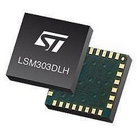
LSM303DLHTR STMicroelectronics, LSM303DLHTR Datasheet - Page 40

LSM303DLHTR
Manufacturer Part Number
LSM303DLHTR
Description
IC ACCELEROMETER 3AXIS 3D 28LGA
Manufacturer
STMicroelectronics
Datasheet
1.STEVAL-MKI063V1.pdf
(47 pages)
Specifications of LSM303DLHTR
Output Type
Digital - I²C
Sensor Type
Accelerometer and Magnetometer
Sensing Axis
Triple
Acceleration
2 g, 4 g, 8 g
Sensitivity
1 mg/digit, 2 mg/digit, 3.9 mg/digit
Package / Case
LGA-28L
Digital Output - Number Of Bits
16 bit
Supply Voltage (max)
3.3 V
Supply Voltage (min)
2.5 V
Maximum Operating Temperature
+ 85 C
Minimum Operating Temperature
- 30 C
Digital Output - Bus Interface
I2C
For Use With
497-10689 - BOARD ADAPTER LSM303DLH DIL24
Lead Free Status / RoHS Status
Lead free / RoHS Compliant
Other names
497-10765-2
LSM303DLHTR
LSM303DLHTR
Available stocks
Company
Part Number
Manufacturer
Quantity
Price
Company:
Part Number:
LSM303DLHTR
Manufacturer:
ST
Quantity:
8 295
Company:
Part Number:
LSM303DLHTR-SMJ
Manufacturer:
ST
Quantity:
8 305
Registers description
9.2.2
9.2.3
40/47
Table 59.
CRB_REG_M (01h)
The configuration register B for setting the device gain. CRB0 through CRB7 indicate bit
locations, with CRB denoting the bits that are in the configuration register. CRB7 denotes
the first bit of the data stream. The number in parentheses indicates the default value of that
bit.
Table 60.
Table 61.
Table 62.
MR_REG_M (02h)
The mode register is an 8-bit register from which data can be read or to which data can be
written. This register is used to select the operating mode of the device. MR0 through MR7
indicate bit locations, with MR denoting the bits that are in the mode register. MR7 denotes
CRB7 to CRB5
CRB7 to CRB5 This bit must be cleared for correct operation
GN2
MS1
0
0
0
1
1
1
1
GN2
0
0
1
1
GN1
0
1
1
0
0
1
1
CRA_REG_M description
CRA_REG register
CRA_REG description
Gain setting
MS0
GN1
0
1
0
1
Gain configuration bits. These bits configure the gain for the device. The gain
configuration is common for all channels
GN0
1
0
1
0
1
0
1
Normal measurement configuration (default). In normal measurement
configuration the device follows normal measurement flow.
Positive bias configuration.
Negative bias configuration.
This configuration is not used
Sensor input
GN0
field range
[Gauss]
±1.3
±1.9
±2.5
±4.0
±4.7
±5.6
±8.1
Doc ID 16941 Rev 1
0
Magnetic sensor operating mode
Gain X/Y and
[LSB/Gauss]
1055
795
635
430
375
320
230
Z
0
[LSB/Gauss]
Gain Z
950
710
570
385
335
285
205
0
0
0xF800–0x07FF
Output range
(-2048–2047)
LSM303DLH
0


