80.91.0.240.0000 FINDER, 80.91.0.240.0000 Datasheet - Page 57
80.91.0.240.0000
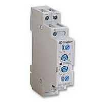
Manufacturer Part Number
80.91.0.240.0000
Description
TIMER, MULTIFUNCTION
Manufacturer
FINDER
Datasheet
1.81.01.0.230.0000.pdf
(165 pages)
Specifications of 80.91.0.240.0000
Contact Configuration
SPCO
Nom Input Voltage
240V
Delay Time Range
0.1s To 20h
Adjustment Type
Screwdriver Slot
Relay Mounting
DIN Rail
Svhc
No SVHC (15-Dec-2010)
Coil Voltage Vac Nom
240V
Coil Voltage Max
240V


ORDERING INFORMATION
POSSIBLE OPTIONS
Option =
Example: a 60 series plug-in relay, 3 CO (3PDT) with coil rated 12 V DC, test button and mechanical indicator.
Series
Type
1 = 8/11 pin plug-in
6 = Faston 187 (mm 4.8x0.8)
No. of poles
2 = 2 pole
3 = 3 pole
Coil version
4 = Current sensing
8 = AC (50/60 Hz)
9 = DC
Coil voltage
see coil specifications
2
with flange mount
0030
0050
0054
AC
6 0
10
7
Option =
.
10
7
1
0060
0070
0074
DC
3
2
.
9
.
0 1 2
60 Series - General Purpose Relays 10 A
ACCESSORIES
060.72: Sheet of marker tags see page 60.
LOCKABLE TEST BUTTON AND MECHANICAL FLAG INDICATOR (0040)
The dual-purpose Finder test button can be used in two ways:
Case 1) The plastic pip (located directly above the test button) remains intact. In this case, when the
test button is pushed, the contacts operate. When the test button is released the contacts return to their
former state.
Case 2) The plastic pip is broken-off (using an appropriate cutting tool). In this case, (in addition to
the above function), when the test button is pushed and rotated, the contacts are latched in the
operating state, and remain so until the test button is rotated back to its former position.
In both cases ensure that the test button actuation is swift and decisive.
Only combinations in the same row are possible
Preferred versions
All versions
A:
0 = Standard
5 = AgNi + 5µm Au
B:
0 = CO
2 = Bifurcated contacts
60.12/13 AC/DC
60.62/63 AC/DC
60.12/13 AC
60.62/63 AC/DC
Contact circuit
Contact material
60.12/13 - 6A only
coil version
coil version
AC
AC
AC
DC
DC
DC
DC
current sensing 0
.
0
A
0
B
A
0
0
A
0
0
5
5
0
0
5
5
0 - 5
4
C
0
D
B
0
0
B
0
0
0 - 2
0 - 2
0
0
0 - 2
0 - 2
0
0
D:
0 = Standard
C:
0 = None
1 = Test button
2 = Mechanical indicator
3 = LED (AC)
4 = Lockable test button +
5 = Lockable test button + LED (AC)
54 = Lockable test button + LED (AC) +
6 = LED + diode (positive to pin 2, DC)
7 = Lockable test button + LED + diode
74 = Lockable test button + LED + diode
Options
Special versions
mechanical indicator
(positive to pin 2)
(positive to pin 2) +
mechanical indicator
mechanical indicator
C
4
0
C
0 - 1 - 2 - 3 - 4 - 5 0
54
0 - 1 - 2 - 3 - 4 - 5 0
54
0 - 1 - 2 - 4 - 6 - 7 0
74
0 - 1 - 2 - 4 - 6 - 7 0
74
4
0
D
0
0
D
/
/
/
/
0
0
55
60
Related parts for 80.91.0.240.0000
Image
Part Number
Description
Manufacturer
Datasheet
Request
R

Part Number:
Description:
JUMPER LINK, 20WAY
Manufacturer:
FINDER
Datasheet:


Part Number:
Description:
INTERFACE RELAY, SPDT-CO, 24VAC/DC
Manufacturer:
FINDER
Datasheet:
Part Number:
Description:
INTERFACE RELAY, SPDT-CO, 24VDC
Manufacturer:
FINDER
Datasheet:

Part Number:
Description:
RELAY, SCREW TERM, 6A, 12VAC/DC
Manufacturer:
FINDER
Datasheet:
Part Number:
Description:
RELAY, SCREW TERM, 6A, 48VAC/DC
Manufacturer:
FINDER
Datasheet:
Part Number:
Description:
RELAY, SCREW TERM, 6A, 125VAC/DC
Manufacturer:
FINDER
Datasheet:
Part Number:
Description:
RELAY, SCREW TERM, 6A, 240VAC/DC
Manufacturer:
FINDER
Datasheet:
Part Number:
Description:
RELAY, SCREW TERM, 6A, 6VDC
Manufacturer:
FINDER
Datasheet:
Part Number:
Description:
RELAY, SCREW TERM, 6A, 12VDC
Manufacturer:
FINDER
Datasheet:
Part Number:
Description:
RELAY, SCRW TER, DPDT, 8A, 24VAC/DC
Manufacturer:
FINDER
Datasheet:
Part Number:
Description:
RELAY, SCREW TERM, DPDT, 8A, 12VDC
Manufacturer:
FINDER
Datasheet:
Part Number:
Description:
RELAY, SCREW TERM, DPDT, 8A, 24VDC
Manufacturer:
FINDER
Datasheet:

Part Number:
Description:
RELAY, SCREWLESS, 6A, 24VDC
Manufacturer:
FINDER
Datasheet: