80.91.0.240.0000 FINDER, 80.91.0.240.0000 Datasheet - Page 156
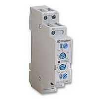
80.91.0.240.0000
Manufacturer Part Number
80.91.0.240.0000
Description
TIMER, MULTIFUNCTION
Manufacturer
FINDER
Datasheet
1.81.01.0.230.0000.pdf
(165 pages)
Specifications of 80.91.0.240.0000
Contact Configuration
SPCO
Nom Input Voltage
240V
Delay Time Range
0.1s To 20h
Adjustment Type
Screwdriver Slot
Relay Mounting
DIN Rail
Svhc
No SVHC (15-Dec-2010)
Coil Voltage Vac Nom
240V
Coil Voltage Max
240V


154
i
TERMINOLOGY & DEFINITIONS
All the following terms indicated in the catalogue are commonly used in technical language. However, occasionally, National European or
International Standards may prescribe the use of different terms, in which case this will be mentioned in the appropriate descriptions that follow.
CONTACT SPECIFICATIONS
CONTACT CONFIGURATION:
TERMINAL MARKING
The European Standard EN 50005 recommends the following numbering for the marking of relay terminals:
- .1 for common contact terminals (e.g. 11, 21, 31…)
- .2 for NC contact terminals (e.g. 12, 22, 32…)
- .4 for NO contact terminals (e.g. 14, 24, 34…)
-
For delayed contacts of timers the numbering will be:
- .5 for common contact terminals (e.g. 15, 25,…)
- .6 for NC contact terminals (e.g. 16, 26, …)
- .8 for NO contact terminals (e.g. 18, 28,…)
IEC 67 and American standards prescribe:
- progressive numbering for terminals (1,2,3,….13,14,..)
- sometimes A and B for coil terminals.
RATED CURRENT - The limiting continuous current, is the highest current that a contact can continuously carry within the prescribed
temperature limits. It also coincides with the limiting cycling capacity, i.e. the maximum current that a contact is capable of making and breaking
under specified conditions.
MAXIMUM PEAK CURRENT - The highest value of inrush current ( 0.5 seconds) that a contact can make and cycle (duty cycle
undergoing any permanent degradation of its characteristics due to generated heat. It also coincides with the limiting making capacity
MAXIMUM BLOCKING VOLTAGE (Solid State Relay) - The maximum level of output voltage at which the output circuit will not be destroyed.
RATED VOLTAGE - The line-to-neutral voltage (derived from nominal voltages of contact loads) used for insulation co-ordination.
MAXIMUM SWITCHING VOLTAGE - The highest voltage level (including tolerances) that the contacts are able to switch according to rated voltage.
RATED LOAD IN AC1 - The maximum AC resistive switching power (in VA) that a contact can make, carry and break repeatedly, according to
utilisation category AC1, EN 60947-4-1 (see Table 1). It is the product of rated current and rated voltage. It is used as the reference load for
electrical life tests.
RATED LOAD IN AC15 - The maximum AC inductive switching power (in VA) that a contact can make, carry and break repeatedly, according to
utilisation category AC15, EN 60947-5-1 (see Table 1).
SINGLE PHASE MOTOR RATING - The nominal value of motor power that a relay can switch according to EN 60947-1, UL 508 and CSA 22.2
n. 14 * The figures are given in kW; the horsepower rating can be calculated by multiplying that value by 1.34 (ie. 0.37 kW = 0.5 HP).
If reversing motor direction, always allow an intermediate break > 300ms, otherwise an excessive inrush peak current (caused from change of
polarity of motor capacitor) may occur, causing contact welding.
RATED LAMPS LOAD - Maximum incandescent and fluorescent lamp ratings for 230 V AC supply voltage. Fluorescent lamps compensated to
BREAKING CAPACITY IN DC1 - The maximum value of DC resistive current that contacts can switch, depending on the value of the load voltage
(see table 1).
MINIMUM SWITCHING LOAD - The minimum values of power, voltage and current that a contact can reliably switch. For example, if minimum
values are 300mW, 5V/5mA:
- with 5V the current must be at least 60mA;
- with 24V the current must be at least 12.5mA;
- with 5 mA the voltage must be at least 60 V.
For gold contact variants, loads no less than 50mW, 5V/2mA are suggested.
With 2 gold contacts in parallel, it is possible to switch 1mW, 0,1V/1mA.
cos
A1 and A2 for coil terminals
Symbol
0.9.
(Normally Closed)
(Normally Open)
Configuration
Make contact
Break contact
Changeover
NO
NC
CO
EU
W
Ö
D
S
GENERAL TECHNICAL INFORMATION
GB
A
B
C
DPST-NO
SPST-NO
nPST-NO
SPST-NC
DPST-NC
nPST-NC
DPDT
USA
SPDT
nPDT
n = number of poles (3,4,…)
0.1) without
Related parts for 80.91.0.240.0000
Image
Part Number
Description
Manufacturer
Datasheet
Request
R

Part Number:
Description:
JUMPER LINK, 20WAY
Manufacturer:
FINDER
Datasheet:


Part Number:
Description:
INTERFACE RELAY, SPDT-CO, 24VAC/DC
Manufacturer:
FINDER
Datasheet:
Part Number:
Description:
INTERFACE RELAY, SPDT-CO, 24VDC
Manufacturer:
FINDER
Datasheet:

Part Number:
Description:
RELAY, SCREW TERM, 6A, 12VAC/DC
Manufacturer:
FINDER
Datasheet:
Part Number:
Description:
RELAY, SCREW TERM, 6A, 48VAC/DC
Manufacturer:
FINDER
Datasheet:
Part Number:
Description:
RELAY, SCREW TERM, 6A, 125VAC/DC
Manufacturer:
FINDER
Datasheet:
Part Number:
Description:
RELAY, SCREW TERM, 6A, 240VAC/DC
Manufacturer:
FINDER
Datasheet:
Part Number:
Description:
RELAY, SCREW TERM, 6A, 6VDC
Manufacturer:
FINDER
Datasheet:
Part Number:
Description:
RELAY, SCREW TERM, 6A, 12VDC
Manufacturer:
FINDER
Datasheet:
Part Number:
Description:
RELAY, SCRW TER, DPDT, 8A, 24VAC/DC
Manufacturer:
FINDER
Datasheet:
Part Number:
Description:
RELAY, SCREW TERM, DPDT, 8A, 12VDC
Manufacturer:
FINDER
Datasheet:
Part Number:
Description:
RELAY, SCREW TERM, DPDT, 8A, 24VDC
Manufacturer:
FINDER
Datasheet:

Part Number:
Description:
RELAY, SCREWLESS, 6A, 24VDC
Manufacturer:
FINDER
Datasheet: