80.91.0.240.0000 FINDER, 80.91.0.240.0000 Datasheet - Page 108
80.91.0.240.0000
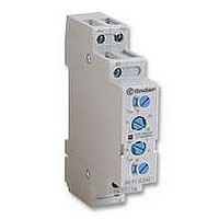
Manufacturer Part Number
80.91.0.240.0000
Description
TIMER, MULTIFUNCTION
Manufacturer
FINDER
Datasheet
1.81.01.0.230.0000.pdf
(165 pages)
Specifications of 80.91.0.240.0000
Contact Configuration
SPCO
Nom Input Voltage
240V
Delay Time Range
0.1s To 20h
Adjustment Type
Screwdriver Slot
Relay Mounting
DIN Rail
Svhc
No SVHC (15-Dec-2010)
Coil Voltage Vac Nom
240V
Coil Voltage Max
240V


85
106
- Plug-in timer relay
- 2, 3 or 4 CO contact available
- Six time scales, from 0.1s to 10h
- Sockets: see 94 series
Contact specifications
Contact configuration
Rated current/Maximum peak current
Rated voltage/Maximum switching voltage V AC
Rated load in AC1
Rated load in AC15 (230 VAC)
Single phase motor rating (230 VAC)
Breaking capacity in DC1:
Minimum switching load
Standard contact material
Supply specifications
Nominal voltage
Rated power AC/DC
Operating range
Technical data
Specified time range
Repeatability
Recovery time
Minimum control impulse
Setting accuracy-full range
Electrical life at rated load in AC1
Ambient temperature range
Protection category
Approvals: (according to type)
3.7
20.6
13.2
3.7
4.1
14.5
27.7
6.3
30/110/220V A
V AC(50/60Hz)
6.7
VA (50Hz)/W
mW(V/mA)
V AC/DC
cycles
kW
AC
DC
VA
VA
ms
ms
°C
%
%
A
85 Series - Miniature Plug-in Timers 5 - 10 A
- 3 Pole, 10A
- AC/DC supply non polarized
- Plug-in for use with 94 series sockets
12 - 24 - 48 - 110…125 (non polarized)
N/–(+)
SW: Symmetrical recycler: ON start
SP: Symmetrical recycler: OFF start
(0.1…1) s, (1…10) s, (10…60) s, (1…10) min, (10…60) min, (1…10) h
31
A2
34
32
9
14
6
3
(0.85…1.1) U
(0.85…1.1)U
wiring diagram
10/0.25/0.1
230…240
–20…+60
300 (5/5)
85.53
250/400
200·10
10/20
2,500
3 CO
AgNi
IP 40
0.37
≤ 20
500
2/2
± 2
± 5
—
21
22
24
8
2
5
3
N
N
11
A1
14
12
7
13
4
1
L/+(–)
C
®
US
- 4 Pole, 5A
- AC/DC supply non polarized
- Plug-in for use with 94 series sockets
12 - 24 - 48 - 110…125 (non polarized)
N/–(+)
SW: Symmetrical recycler: ON start
SP: Symmetrical recycler: OFF start
GOST
41
A2
44
42
12
14
8
4
(0.85…1.1)U
(0.85…1.1)U
wiring diagram
5/0.25/0.1
31
32
230…240
300 (5/5)
–20…+60
34
250/250
85.54
150·10
11
3
7
1,250
0.125
4 CO
5/20
AgNi
IP 40
≤ 20
250
2/2
± 2
± 5
—
21
24
22
10
6
3
2
N
N
11
A1
14
12
9
13
5
1
L/+(–)
Related parts for 80.91.0.240.0000
Image
Part Number
Description
Manufacturer
Datasheet
Request
R

Part Number:
Description:
JUMPER LINK, 20WAY
Manufacturer:
FINDER
Datasheet:


Part Number:
Description:
INTERFACE RELAY, SPDT-CO, 24VAC/DC
Manufacturer:
FINDER
Datasheet:
Part Number:
Description:
INTERFACE RELAY, SPDT-CO, 24VDC
Manufacturer:
FINDER
Datasheet:

Part Number:
Description:
RELAY, SCREW TERM, 6A, 12VAC/DC
Manufacturer:
FINDER
Datasheet:
Part Number:
Description:
RELAY, SCREW TERM, 6A, 48VAC/DC
Manufacturer:
FINDER
Datasheet:
Part Number:
Description:
RELAY, SCREW TERM, 6A, 125VAC/DC
Manufacturer:
FINDER
Datasheet:
Part Number:
Description:
RELAY, SCREW TERM, 6A, 240VAC/DC
Manufacturer:
FINDER
Datasheet:
Part Number:
Description:
RELAY, SCREW TERM, 6A, 6VDC
Manufacturer:
FINDER
Datasheet:
Part Number:
Description:
RELAY, SCREW TERM, 6A, 12VDC
Manufacturer:
FINDER
Datasheet:
Part Number:
Description:
RELAY, SCRW TER, DPDT, 8A, 24VAC/DC
Manufacturer:
FINDER
Datasheet:
Part Number:
Description:
RELAY, SCREW TERM, DPDT, 8A, 12VDC
Manufacturer:
FINDER
Datasheet:
Part Number:
Description:
RELAY, SCREW TERM, DPDT, 8A, 24VDC
Manufacturer:
FINDER
Datasheet:

Part Number:
Description:
RELAY, SCREWLESS, 6A, 24VDC
Manufacturer:
FINDER
Datasheet: