80.91.0.240.0000 FINDER, 80.91.0.240.0000 Datasheet - Page 17
80.91.0.240.0000
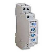
Manufacturer Part Number
80.91.0.240.0000
Description
TIMER, MULTIFUNCTION
Manufacturer
FINDER
Datasheet
1.81.01.0.230.0000.pdf
(165 pages)
Specifications of 80.91.0.240.0000
Contact Configuration
SPCO
Nom Input Voltage
240V
Delay Time Range
0.1s To 20h
Adjustment Type
Screwdriver Slot
Relay Mounting
DIN Rail
Svhc
No SVHC (15-Dec-2010)
Coil Voltage Vac Nom
240V
Coil Voltage Max
240V


F 40
Electrical life vs AC1 load.
1 - Type 40.52 (8 A)
2 - Type 40.31 - 40.51 (10 A)
2 -
COIL SPECIFICATIONS
DC VERSION DATA (0.65 W standard)
AC VERSION DATA
CONTACT SPECIFICATIONS
Nominal
Nominal
voltage
voltage
110
10
10
10
110
120
230
240
Type 40.61 (16 A)
U
U
12
14
18
21
24
28
36
48
60
90
V
V
12
24
48
60
N
N
7
6
5
5
6
7
9
6
0
9.005
9.006
9.007
9.009
9.012
9.014
9.018
9.021
9.024
9.028
9.036
9.048
9.060
9.090
9.110
8.006
8.012
8.024
8.048
8.060
8.110
8.120
8.230
8.240
code
code
Coil
Coil
4
LOAD RATED CURRENT (A)
184
192
10.2
13.1
15.3
17.5
20.5
26.3
35
43.8
65.7
80.3
Operating range
Operating range
U
U
19.2
38.4
48
88
96
3.65
4.4
5.1
6.6
8.8
V
V
min
4.8
9.6
min
1
8
121
132
253
264
135
165
U
U
13.2
26.4
52.8
66
40 Series - Miniature P.C.B. Relays 8 - 10 - 16 A
10.5
13.5
18
21
27
31.5
36
42
54
72
90
max
V
max
V
6.6
7.5
9
12
Resistance Rated coil
Resistance Rated coil
12,500
18,000
28,000
31,500
1,200
2,000
3,500
5,500
1,350
2,100
6,900
9,000
R
125
220
300
500
700
900
R
Ω
Ω
320
38
55
75
21
80
2
16
I at U
consumption
consumption
130
109
I at U
168
94
72
55
47
36
30
27
23
18
14
11
mA
90
45
21
16.8
N
mA
7.2
6.2
9.4
8.4
5
4.1
(50Hz)
N
** R
DC VERSION DATA (0.5 W sensitive)
*U
AC/DC VERSION DATA (bistable)
Nominal
voltage
Nominal
voltage
110
min
U
110
DC =
12
24
48
U
V
N
12
14
18
21
24
28
36
48
60
90
V
5
6
N
= 0.8 U
H 40
Breaking capacity for DC1 load.
1 - Type 40.61
2 - Type 40.31 - 40.51
3 - Type 40.52
A - Load applied to 1 contact
B - Load applied to 2 contacts in series
• When switching a resistive load (DC1) having voltage and
current values under the curve the expected electrical life is
≥ 100·10
• In case of DC13 loads the connection of a diode in parallel with
the load will permit the same electrical life as for a DC1 load.
Note: the release time of load will be increase.
5
6
7
9
Resistance in DC, R
0.2
0.1
20
10
6.005
6.006
6.012
6.024
6.048
6.110
6
4
2
1
Coil
20
7.005
7.006
7.007
7.009
7.012
7.014
7.018
7.021
7.024
7.028
7.036
7.048
7.060
7.090
7.110
N
code
Coil
3
for 40.61
A
cycles.
Operating range Resistance Rated coil DC: Release
U
19.2
38.4
88
60
V
min
4
4.8
9.6
U
Operating range
10.2
13.2
15.4
17.5
20.5
26.3
35
43.8
65.7
80.3
AC
min
3.7
4.4
5.1
6.6
8.8
V
B
**U
*
= 1.3 x R
DC VOLTAGE (V)
121
U
13.2
26.4
52.8
100
max
V
max
5.5
6.6
U
105
157
192
= 1.5 U
max
10.5
12.2
15.8
21
24.5
31.5
36.9
42
49
63
84
DC
V
8.8
11,000
**
2,100
, 1W
140
R
130
520
Ω
23
33
N
Resistance Rated coil
16,200
23,500
for 40.61
1,200
1,600
2,600
4,800
7,200
consumption resistance**
100
160
300
400
650
900
R
Ω
I at U
50
75
215
165
mA
83
40
21
10
180
N
consumption
16,500
100
I at U
3,600
80
70
56
40
35
27.7
23.4
20
17.5
13.8
10
mA
R
8.4
5.6
4.7
220
Ω
220
910
DC
37
62
N
1
2
3
15
40
Related parts for 80.91.0.240.0000
Image
Part Number
Description
Manufacturer
Datasheet
Request
R

Part Number:
Description:
JUMPER LINK, 20WAY
Manufacturer:
FINDER
Datasheet:


Part Number:
Description:
INTERFACE RELAY, SPDT-CO, 24VAC/DC
Manufacturer:
FINDER
Datasheet:
Part Number:
Description:
INTERFACE RELAY, SPDT-CO, 24VDC
Manufacturer:
FINDER
Datasheet:

Part Number:
Description:
RELAY, SCREW TERM, 6A, 12VAC/DC
Manufacturer:
FINDER
Datasheet:
Part Number:
Description:
RELAY, SCREW TERM, 6A, 48VAC/DC
Manufacturer:
FINDER
Datasheet:
Part Number:
Description:
RELAY, SCREW TERM, 6A, 125VAC/DC
Manufacturer:
FINDER
Datasheet:
Part Number:
Description:
RELAY, SCREW TERM, 6A, 240VAC/DC
Manufacturer:
FINDER
Datasheet:
Part Number:
Description:
RELAY, SCREW TERM, 6A, 6VDC
Manufacturer:
FINDER
Datasheet:
Part Number:
Description:
RELAY, SCREW TERM, 6A, 12VDC
Manufacturer:
FINDER
Datasheet:
Part Number:
Description:
RELAY, SCRW TER, DPDT, 8A, 24VAC/DC
Manufacturer:
FINDER
Datasheet:
Part Number:
Description:
RELAY, SCREW TERM, DPDT, 8A, 12VDC
Manufacturer:
FINDER
Datasheet:
Part Number:
Description:
RELAY, SCREW TERM, DPDT, 8A, 24VDC
Manufacturer:
FINDER
Datasheet:

Part Number:
Description:
RELAY, SCREWLESS, 6A, 24VDC
Manufacturer:
FINDER
Datasheet: