80.91.0.240.0000 FINDER, 80.91.0.240.0000 Datasheet - Page 164
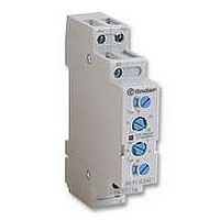
80.91.0.240.0000
Manufacturer Part Number
80.91.0.240.0000
Description
TIMER, MULTIFUNCTION
Manufacturer
FINDER
Datasheet
1.81.01.0.230.0000.pdf
(165 pages)
Specifications of 80.91.0.240.0000
Contact Configuration
SPCO
Nom Input Voltage
240V
Delay Time Range
0.1s To 20h
Adjustment Type
Screwdriver Slot
Relay Mounting
DIN Rail
Svhc
No SVHC (15-Dec-2010)
Coil Voltage Vac Nom
240V
Coil Voltage Max
240V


162
i
+
–
+
–
Voltage-current characteristic when
switching an ohmic load (fig. 1).
Voltage-current characteristic when
switching a relay coil ( fig. 2).
99.01.9.xxx.99 only
99.80.9.xxx.99 only
99.01.9.xxx.79 only
99.01.3.000.00 only
99.80.3.000.00 only
99.01.2.000.00 only
+
--
--
+
R
A1
A2
A1
A2
+
R
--
--
+
D
D
U
U
L
A1
A2
A1
A2
I
I
R
D
D
R
D
D
U
U
I
I
Diagrams
LD
LD
+
--
ON
ON
A1
A2
+
--
99 Series - Coil indication and suppression modules
99.02.9.xxx.99 only
99.02.9.xxx.79 only
99.02.2.000.00 only
99.02.3.000.00 only
OFF
OFF
A2
A1
VDR
+
+
+
--
--
+
--
--
A1
A1
A1
A2
R
A2
A2
A1
A2
R
R
t
t
D
D
C
D1
D1
D1
D
D
D1
Switching Relay Coils.
When switching a resistive load, the current follows
the phase of the voltage directly (Fig 1).
When switching relay coils the current and voltage
waveforms are different due to the inductive nature
of the coil (Fig 2). A brief explanation of this
mechanism is as follows.
On energisating the coil, the build up of the
magnetic field gives rise to counter electromotive
forces which in turn delay the rise in coil current.
On de-energisation, the sudden interruption of the
coil current causes a sudden collapse of the
magnetic field, which in turn induces a high voltage
of reverse polarity across the coil. This reverse
polarity voltage peak can reach a value typically 15
times higher than the supply voltage, and as a
consequence can disturb or destroy electronic
devices.
LD
LD
R
D
D
R
R
LD
LD
Functions
GREEN LED +DIODE MODULE (STANDARD POLARITY)
Recovery diode modules + LED are used for DC only. The reverse voltage peaks of the
coil are short circuited by the recovery diode (positive to terminal A1).
The release time increases by an approximate factor of 3.
If an increase of the release time is undesirable use a Varistor or RC module.
The LED indicator lights up when the coil is energized.
GREEN LED +DIODE MODULE (INVERTED POLARITY)
Recovery diode modules + LED are used for DC only. The reverse voltage peaks of the
coil are short circuited by the recovery diode (positive to terminal A2).
The release time increases by an approximate factor of 3.
If an increase of the release time is undesirable use a Varistor or RC module.
The LED indicator lights up when the coil is energized.
GREEN LED + VARISTOR
LED modules + Varistor are used for both AC and DC coils.
The reverse voltage peaks of the relay coil are limited by the Varistor to approximately
2.5 times the nominal voltage of the supply. When using DC coils it is essential that
positive is connected to terminal A1. The relay release time increases insignificantly.
GREEN LED
LED modules are used for AC and DC.
The LED indicator lights up when the coil is energized.
When using DC it is essential that positive is connected to terminal A1.
DIODE MODULE (STANDARD POLARITY)
Recovery diode modules are used for DC only. The reverse voltage
peaks of the coil are short circuited by the recovery diode (positive to terminal A1).
The release time increases by an approximate factor of 3.
If an increase of the release time is undesirable use a Varistor or RC module.
DIODE MODULE (INVERTED POLARITY)
Recovery diode modules are used for DC only. The reverse voltage
peaks of the coil are short circuited by the recovery diode (positive to terminal A2).
The release time increases by an approximate factor of 3.
If an increase of the release time is undesirable use a Varistor or RC module.
RC MODULE
RC circuit modules are used for AC and DC coils. The reverse voltage peaks
of the coil are limited by the RC module to approximately 2.5 times the
nominal voltage of the supply. The relay release time increases insignificantly.
RESIDUAL CURRENT BYPASS MODULE
Bypass modules are advisable if 110 or 230v AC relays show any tendency to fail to
release. Failure to release can be caused by residual currents from AC proximity switches
or inductive coupling caused through long parallel lying AC control lines.
To counteract this potentially damaging effect,
relays coils can be suppressed with a Diode, a
Varistor (voltage dependent resistor) or a RC
(resistor/capacitor) module – dependent on the
operating voltage. (See below for descriptions of
the
Whilst the above description is based on the
working of a DC coil, the reverse polarity voltage
peak on de-energisation applies similarly to AC
coils. However, when energising AC coils there will
also be a coil inrush current of 1.3 to 1.7 times the
nominal coil current – dependent on coil size. If
coils are fed via a transformer (and particularly if
several are energised at the same time) then this
may need to taken into account when calculating
the VA rating of the transformer.
various
Modules
available.)
Related parts for 80.91.0.240.0000
Image
Part Number
Description
Manufacturer
Datasheet
Request
R

Part Number:
Description:
JUMPER LINK, 20WAY
Manufacturer:
FINDER
Datasheet:


Part Number:
Description:
INTERFACE RELAY, SPDT-CO, 24VAC/DC
Manufacturer:
FINDER
Datasheet:
Part Number:
Description:
INTERFACE RELAY, SPDT-CO, 24VDC
Manufacturer:
FINDER
Datasheet:

Part Number:
Description:
RELAY, SCREW TERM, 6A, 12VAC/DC
Manufacturer:
FINDER
Datasheet:
Part Number:
Description:
RELAY, SCREW TERM, 6A, 48VAC/DC
Manufacturer:
FINDER
Datasheet:
Part Number:
Description:
RELAY, SCREW TERM, 6A, 125VAC/DC
Manufacturer:
FINDER
Datasheet:
Part Number:
Description:
RELAY, SCREW TERM, 6A, 240VAC/DC
Manufacturer:
FINDER
Datasheet:
Part Number:
Description:
RELAY, SCREW TERM, 6A, 6VDC
Manufacturer:
FINDER
Datasheet:
Part Number:
Description:
RELAY, SCREW TERM, 6A, 12VDC
Manufacturer:
FINDER
Datasheet:
Part Number:
Description:
RELAY, SCRW TER, DPDT, 8A, 24VAC/DC
Manufacturer:
FINDER
Datasheet:
Part Number:
Description:
RELAY, SCREW TERM, DPDT, 8A, 12VDC
Manufacturer:
FINDER
Datasheet:
Part Number:
Description:
RELAY, SCREW TERM, DPDT, 8A, 24VDC
Manufacturer:
FINDER
Datasheet:

Part Number:
Description:
RELAY, SCREWLESS, 6A, 24VDC
Manufacturer:
FINDER
Datasheet: