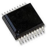
AS5134-ASSU austriamicrosystems, AS5134-ASSU Datasheet - Page 34

AS5134-ASSU
Manufacturer Part Number
AS5134-ASSU
Description
ENCODER, MAGNETIC, ROTARY, 8BIT, 20SSOP
Manufacturer
austriamicrosystems
Datasheet
1.AS5134-ASSU.pdf
(39 pages)
Specifications of AS5134-ASSU
Brief Features
9-Bit Multiturn Counter, User Programmable Zero Position And Sensitivity
Supply Voltage Range
4.5V To 5.5V
Operating Temperature Range
-40°C To +140°C
Digital Ic Case
RoHS Compliant
Ic Function
Programmable High Speed Magnetic Rotary Encoder
Rohs Compliant
Yes
AS5134
Data Sheet - A p p l i c a t i o n I n f o r m a t i o n
Table 12. Parameter and Features List
www.austriamicrosystems.com
PWM output
Interface hardware
Maximum speed; no missing codes
Alignment tolerance
Normal operating Current consumption
Power-Up time
Serial Interface read options
Zero Position Programming
Serial interface program options
Serial interface write options (temporary write; will
be lost with POR)
IC package
Magnetic range software indicator
Magnetic input field range [mT]
BLDC Outputs
BLDC outputs
BLDC pole pair options
Hysteresis on BLDC outputs
Switching positions
Parameter
2µs / step. 360º angle range in all modes.
Minimum pos. pulse width (@0º) = 16µs (8 LSB; tbd)
Minimum neg. pulse width (@359º) = 16µs (8 LSB; tbd)
Pulse width @0º = 16µs, Pause = 734µs
Pulse width @1º = 18µs, Pause = 732µs
Pulse width @2º = 20µs, Pause = 730µs
………..
Pulse width @359º = 734µs, Pause = 16µs
In case of an error (LOCK = Low), the pulse width is 8 µs (4
LSB), pause = 742µs for all angles.
Incremental ABI interface: 3 pins
BLDC UWV interface: 3 pins
Absolute interface: 2 or 3 pins
All outputs are available at the same time on separate pins
25.000 rpm
+/- 0.25 mm (reference to package center)
Typ 14mA; max 22mA
≤1.3 ms from cold start (no AGC),
≤4.1ms from cold start (AGC locked)
<0.5ms from low power mode
360-step Angle (8.5-bit), 6-bit AGC, 9-bit Multiturn,
ADC Lock
in OTP
Incremental mode(quad ABI, step/dir)
BLDC pole pairs (1,2,3,4,5,6)
Zero Position
Hall sensor sensitivity
Incremental mode(quad ABI, step/dir)
BLDC pole pairs (1,2,3,4,5,6)
Zero Position
Hall sensor sensitivity
Multiturn counter reset to 00
Low power mode (on/off)
SSOP-20
Field strength (AGC) readable through digital interface
20 – 80 mT
3 separate digital outputs: U,V,W
Selectable for 1,2,3,4,5,6, pole pairs
Same as incremental output hysteresis
Revision 1.8
Pole pairs
1
2
3
AS5134
Switching position steps
60º
30º
20º
34 - 39


