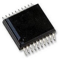
AS5134-ASSU austriamicrosystems, AS5134-ASSU Datasheet - Page 33

AS5134-ASSU
Manufacturer Part Number
AS5134-ASSU
Description
ENCODER, MAGNETIC, ROTARY, 8BIT, 20SSOP
Manufacturer
austriamicrosystems
Datasheet
1.AS5134-ASSU.pdf
(39 pages)
Specifications of AS5134-ASSU
Brief Features
9-Bit Multiturn Counter, User Programmable Zero Position And Sensitivity
Supply Voltage Range
4.5V To 5.5V
Operating Temperature Range
-40°C To +140°C
Digital Ic Case
RoHS Compliant
Ic Function
Programmable High Speed Magnetic Rotary Encoder
Rohs Compliant
Yes
AS5134
Data Sheet - A p p l i c a t i o n I n f o r m a t i o n
8 Application Information
Benefits of AS5134
AS5134 Parameter and Features List
Table 12. Parameter and Features List
www.austriamicrosystems.com
Supply Voltage
Resolution
Incremental outputs (ABI)
BLDC outputs
Absolute output
Daisy Chain mode
Automotive qualification
Chip Identifier
Ambient temperature
ESD protection
Propagation delay (in locked state)
Transition noise (rms; 1 sigma)
Integral Nonlinearity (INL),
centered magnet
Multiturn Counter
Low power mode
Complete system-on-chip, no angle calibration required
Flexible system solution provides absolute serial, ABI, UVW and PWM outputs
Ideal for applications in harsh environments due to magnetic sensing principle
High reliability due to non-contact sensing
Robust system, tolerant to horizontal misalignment, airgap variations, temperature variations and external mag-
netic fields
Parameter
4.5 to 5.5 V
8.5 bit (360 steps, 1º per step)
ABI quadrature: 90 ppr, (default)
step/direction: 180 ppr (OTP option)
fixed pulse width: 360ppr
UVW ; selectable for 1,2,3,4,5,6, pole pairs
Serial 2-wire (DCLK,DIO) with timeout sync
Serial 3-wire (DCLK, CS, DIO)
PWM output
Available for 2-wire and 3-wire serial modes
AEC Q-100, grade 1
18 bit
-40 to +140ºC
±2kV
Max 22µs
0.24º
+/-2º
9-bit (+256/-255 turns).
Automatically updated during active mode at every 360º-/0º-
transition in each rotating direction.
The multiturn counter can be accessed over the serial interface
and is reset with a power-on-reset.
It will be frozen at the last valid state in low power mode.
Non-operational. Last status is frozen in Low power mode to
allow low power consumption and fast startup from low power
mode to operating mode.
Serial interface is active in low power mode to allow wakeup
over the serial interface.
PWM, incremental and BLDC outputs are invalid in low power
mode, they remain at their last valid state.
Current consumption in low power mode: typ. 30µA
Revision 1.8
AS5134
33 - 39


