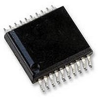
AS5134-ASSU austriamicrosystems, AS5134-ASSU Datasheet - Page 12

AS5134-ASSU
Manufacturer Part Number
AS5134-ASSU
Description
ENCODER, MAGNETIC, ROTARY, 8BIT, 20SSOP
Manufacturer
austriamicrosystems
Datasheet
1.AS5134-ASSU.pdf
(39 pages)
Specifications of AS5134-ASSU
Brief Features
9-Bit Multiturn Counter, User Programmable Zero Position And Sensitivity
Supply Voltage Range
4.5V To 5.5V
Operating Temperature Range
-40°C To +140°C
Digital Ic Case
RoHS Compliant
Ic Function
Programmable High Speed Magnetic Rotary Encoder
Rohs Compliant
Yes
AS5134
Data Sheet - D e t a i l e d D e s c r i p t i o n
Serial 2-Wire Connection (R/W Mode)
By connecting the configuration input C2 to VDD, the AS5134 is configured to 2-wire data transmission mode. Only
Clock (DCLK) and Data (DIO) signals are required. A Chip Select (CS) signal is automatically generated by the DX
output, when a time-out of DCLK occurs (typ. 20µs).
Note: Read-only mode is also possible in this configuration.
Figure 6. 2-Wire R/W Mode
Serial 2-Wire Differential SSI Connection
With the addition of a RS-422 / RS-485 transceiver, a fully differential data transmission, according to the 21-bit SSI
interface standard is possible. To be compatible with this standard, the DCLK signal must be inverted. This is done by
reversing the Data+ and Data- lines of the transceiver.
Note: This type of transmission is read-only.
www.austriamicrosystems.com
DCLK
DIO
DIO
DX
CS
t0
1
t1
CMD4
VSS
2
VDD
+5V
CMD3
command phase
3
VDD
VSS
CMD2
Output
I/O
4
CMD1
5
Revision 1.8
CMD0
t5
t6
6
DCLK
DIO
D15
data phase
7
C2
VDD
VSS
D14
8
100n
D1
timeout phase
22
D0
t
TO
DIO read
DIO write
12 - 39


