AS5134-ASSU austriamicrosystems, AS5134-ASSU Datasheet - Page 27

AS5134-ASSU
Manufacturer Part Number
AS5134-ASSU
Description
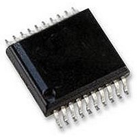
ENCODER, MAGNETIC, ROTARY, 8BIT, 20SSOP
Manufacturer
austriamicrosystems
Datasheet
1.AS5134-ASSU.pdf
(39 pages)
Specifications of AS5134-ASSU
Brief Features
9-Bit Multiturn Counter, User Programmable Zero Position And Sensitivity
Supply Voltage Range
4.5V To 5.5V
Operating Temperature Range
-40°C To +140°C
Digital Ic Case
RoHS Compliant
Ic Function
Programmable High Speed Magnetic Rotary Encoder
Rohs Compliant
Yes
AS5134
Data Sheet - D e t a i l e d D e s c r i p t i o n
As shown in
Figure 19
(grey zone), the Hall elements are located on the chip at a circle with a radius of 1.1mm. Since
the difference between two opposite Hall sensors is measured, there will be no difference in signal amplitude when the
magnet is perfectly centered or if the magnet is misaligned in any direction as long as all Hall elements stay within the
linear range.
For the 6mm magnet (shown in
Figure
19), the linear range has a radius of 1.6mm, hence this magnet allows a radial
misalignment of 0.5mm (1.6mm linear range radius; 1.1mm Hall array radius). Consequently, the larger the linear
range, the more radial misalignment can be tolerated. By contrast, the slope of the linear range decreases with
increasing magnet diameter, as the poles are further apart. A smaller slope results in a smaller differential signal, which
means that the magnet must be moved closer to the IC (smaller airgap) or the amplification gain must be increased,
which leads to a poorer signal – to – noise ratio. More noise results in more jitter at the angle output. A good
compromise is a magnet diameter in the range of 5…8mm.
Small Diameter Magnet (<6mm)
Large Diameter Magnet (>6mm)
+++ stronger differential signal =
+++ wider linear range =
good signal / noise ratio,
larger horizontal misalignment area
larger airgaps
-- weaker differential signal =
--- shorter linear range =
poorer signal / noise ratio,
smaller horizontal misalignment area
smaller airgaps
Figure 19. Vertical Magnetic Field across the center of a Cylindrical Magnet
Bz; 6mm magnet @ y=0; z=1mm
Hall elements (side view)
X -displacement [mm]
www.austriamicrosystems.com
Revision 1.8
27 - 39


